40
F O R M
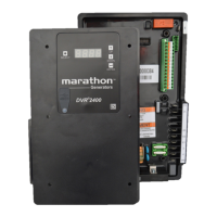
DVR
®
2400 and DVR
®
2500 Digital Voltage Regulator
Installation, Operation and Maintenance Manual
SB0056E
Revised
November 2018
Regal Beloit America, Inc.
100 East Randolph Street
Wausau, WI 54402-8003
www.regalbeloit.com/Brands/
Marathon-Generators
DVRPORTAL™
GRAPHICAL USER INTERFACE (GUI)
The DVRPortal
™
software offers a means of programming the regulator and
monitoring generator performance. This Windows
®
application software is
available as a free download from the website https://www.marathongen-
erators.com/generators/dvrDownload.jsp. With this software, the user will
be able to change all of the programmable parameters.
DVRPortal™ software consists of a header, and four panels (Metering,
Configuration, Identification and Event Log). The header displays regula-
tor status and basic administration functions. The Metering tab displays
metered quantities and fault information. The Configuration tab permits
editing of all programmable parameters. The Identification tab contains
information specific to the regulator and allows for custom identification
tags. The Event Log tab allows user to access the Event Log information
saved in the regulator memory.
PARAMETER EDIT BUTTONS
On some of the parameter selection screens, you will find the following
buttons:
Apply – Pressing this button sends the values in the currently active tab of
the DVRPortal software to the regulator RAM.
Undo – Pressing this button displays the values just prior to the last edit in
the currently active tab of the DVRPortal software. These values can then
be sent to the regulator RAM by clicking on the Apply button.
Refresh – Pressing this button loads the values that are presently in the
regulator RAM into the currently active tab of the DVRPortal software.
HEADER (1)
This is the main panel in the DVRPortal software. It is present on all
screens.
Regulator Status (1a)
The header panel includes four indicators that enunciate the regulator
status:
• Run State: If the regulator is in a run state, the header will display
a green RUNV/ RUNI/ RUNP indicator, respectively, for Voltage/Field
Current/ VAR or PF regulation.
• Alarm State: If the regulator is in an alarm state, the header will dis-
play a yellow alarm indicator.
• Fault State: If the regulator is in a fault state, the header will display
a red fault indicator.
• STBY: If the regulator is in Standby State, the header will display
STBY indicator.
• IDLE: If the regulator is in Idle State, the header will display IDLE
indicator.
• STRT: If the regulator is in Soft Start State, the header will display
STRT indicator.
• FLSH: If the regulator is in Field Flashing state, the header will dis-
play FLSH Indicator.
Configuration tabs (1b)
The configuration tabs are buttons that access the Metering, Configura-
tion, Identification and Event Log tabs.
Administrative Buttons (1c)
The administrative buttons provide communication port settings, file ma-
nipulation and storing to regulator non-volatile memory.
1 1a 1b 1c 1d

 Loading...