Reversing
the
Phase
Sequence
of
a
Rewound
Stator. There have been many instances
where
a
repair facility will rewind either a main stator
or
an exciter stator
on
a MAC generator, and
then
not
be
able
to
generate a voltage
at
the terminals during test running. In almost every case
of
this nature,
the problem
is
in
the
phase sequence
of
the rewound stator.
A briefreview
of
the Principals
of
Operation
will
show that both the main stator and the exciter
stator are interconnected, and that current is generated in the main stator, flows through
the
exciter
stator and
out
to
the load. Since both the main rotor and the exciter rotor are
on
the same shaft, and
turning in the same direction,
the
phase
Sffiuence
ofthe
exciter
stator
must
be
opposite
to
that
of
the
main
stator
or
the
unit
will
not
build
up
voltage.
To
correct this problem, you will have
to
reverse the phase sequence
of
the rewound stator.
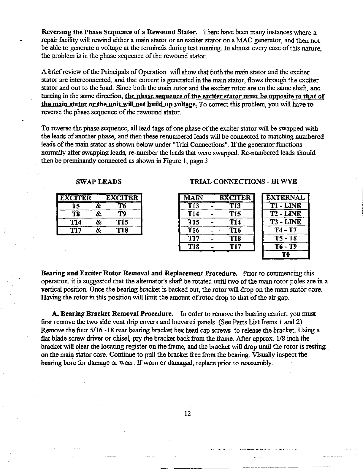
To
reverse the phase sequence, all lead tags
of
one phase
of
the exciter stator will
be
swapped
with
the leads
of
another phase, and then these renumbered leads will
be
connected
to
matching numbered
leads
of
the main stator as shown below under "Trial Connections".
If
the generator functions
nonnally after swapping leads, re-number
the
leads that were swapped. Re-numbered leads should
then be preminantly connected as shown in Figure I, page 3.
SWAP LEADS
TRIAL
CONNECTIONS
-
Hi
WYE
EXCITER
EXCITER
MAIN
EXCITER
EXTERNAL
TS
&
T6
T13
-
T13
Tl-LINE
T8
&
T9 T14
-
TIS
TI-LINE
TI4
&
TIS
TIS
-
T14
TI-LINE
T17 &
TIS
T16
-
T16
T4-T7
T17
-
TIS
TS-TS
TIS
-
T17
T6-T9
TO
Bearing
and
Exciter
Rotor
Removal
and
Replacement
Procedure.
Prior
to
commencing this
operation, it is suggested
that
the alternator's shaft be rotated until two
of
the main
rotor
poles
are
in a
vertical position. Once
the
bearing bracket is backed out, the rotor will drop
on
the main stator core.
Having the rotor in this position
will limit the amount
ofrotor
drop
to
that
of
the
air gap. ·
A.
Bearing
Bracket
Removal
Procedure.
In
order
to
remove the bearing canier, you
must
first
remove the two side vent drip covers and louvered panels. (See Parts List Items I and 2).
Remove the four 5/16 -18 rear bearing bracket hex head cap screws
to
release the bracket. Using a
fiat
blade screw driver
or
chisel, pry the bracket back from the frame. After approx. 1/8 inch the
bracket will clear the locating register
on
the
frame, and the bracket will drop until the
rotor
is resting
on
the main stator core. Continue
to
pull
the
bracket free from
the
bearing. Visually inspect
the
bearing bore for damage
or
wear.
If
worn
or
damaged, replace prior
to
reassembly.
12
 Loading...