NOTE:
There is an
"0"
ring installed in the bearing bore
of
the bearing bracket. Inspect this 0 ring
for wear
or
damage, and replace
if
necessary.
B.
Bearing
Removal
Procedure.
Visually inspect the bearing for obvious wear
or
damage
before removing.
Using a bearing puller, remove
the
bearing.
If
possible, insure that
the
puller is
against the inner race
of
the bearing
to
prevent damaging the bearing.
C.
Bearing
Replacement.
ALWAYS
install the same type and size bearing that was supplied
as original equipment. Order by part number from the parts list, and include the unit serial number
and
part number when ordering. Heat the bearing
to
a maximum
of
212°F in an oven. Apply a thin
coat
of
clean lubricating oil
to
the press-fit area
of
the rotor shaft. Using suitable heat resistant
gloves, install the bearing over the end
of
the shaft until it seats against the shaft shoulder. The
bearing should slide
on
the shaft and
be
seated without excessive force. Should the bearing bind
on
the shaft prior
to
being seated against the shoulder, a piece
of
tubing slightly larger than
the
press-fit
area can
be
used
to
drive the bearing home. Using light taps with a soft mallet, apply pressure
to
the
inner race only.
Testing Diodes
on
the
260
Frame
Rotating
Rectifier
Assembly. Following the procedures in
Paragraph A above, remove the
bearing carrier. The rotating rectifier assembly is in-board
of
the
bearing and is mounted
on
the exciter rotor core. Refer
to
Figure 4 for reference
to
diode polarity and
part identification.
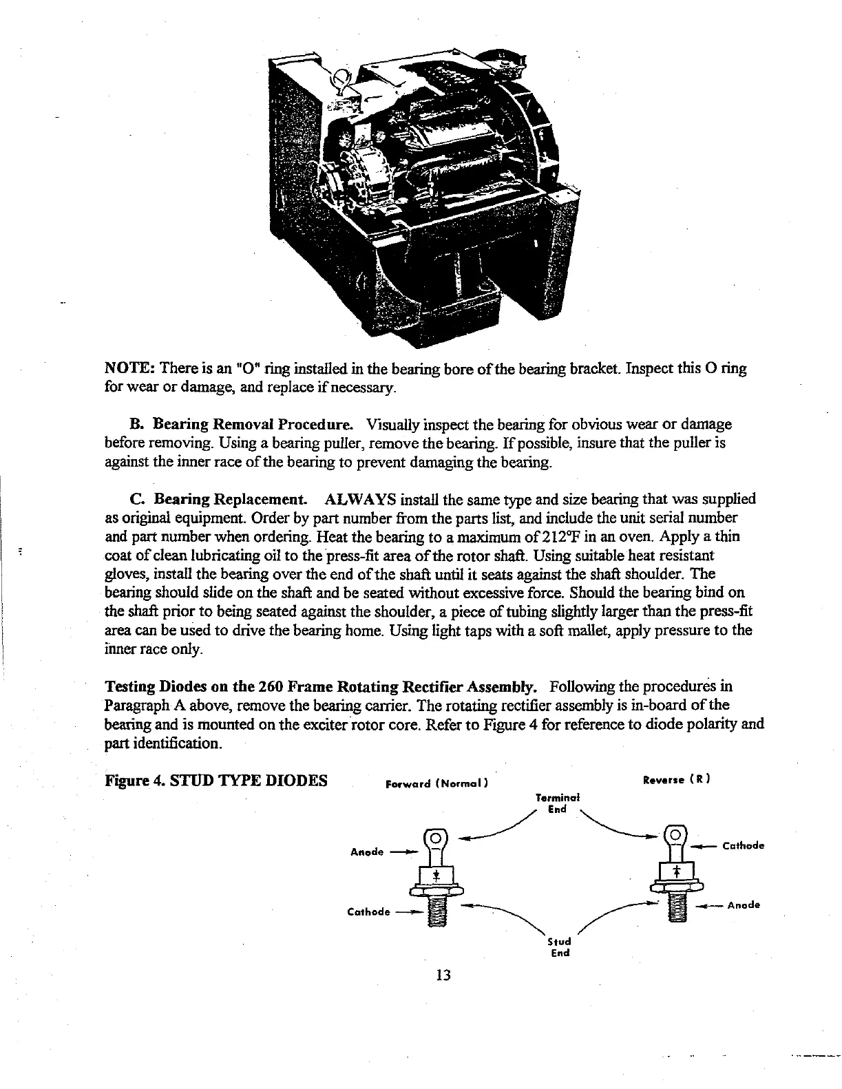
Figure 4.
STUD
TYPE
DIODES
Forward
(Normal)
Reverse {
R)
Anode -
Terminal
Q
__/
End
."'----
13
~~
Stud
End