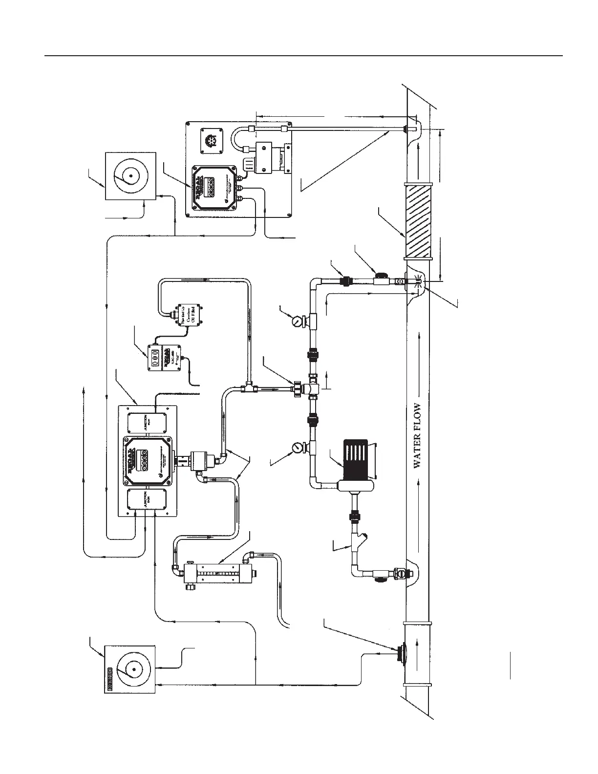
DRAWING NO. 3 — TYPICAL INSTALLATION
Compound Loop Control System
Flow Recorder
(BY OTHERS)
4-20 Milliamp Analog Output Signal
Residual Analog Input Signal (4-20mA DC)
Vacuum Tubing
GAS FLOW from
Vacuum Regulator
REGAL 7500
Remote Meter
Assembly
Isolation Valve (Typ.)
(BY OTHERS)
Booster Pump
(BY OTHERS)
REGAL Ejector
Assembly
Y-Strainer
(BY OTHERS)
Pipe Union (Typ.)
(BY OTHERS)
Gauge for Supply
Pressure (Ps)
Gauge for
Back Pressure
(Pb)
REGAL Model CRA-5000
Residual Analyzer
REGAL VAC-1000
Vacuum Monitor
Static Mixer
(BY OTHERS)
Lag Time (T2)
Lag Time (T1)
Lag Time
(T3)
Chlorine Solution Injection into Center of Main Line
120/240 VAC
50/60 Hz
120/240 VAC
50/60 Hz
120/240 VAC
50/60 Hz
120/240 VAC
50/60 Hz
REGAL SMARTVALVE™
Model 7009
Residual Recorder
(BY OTHERS)
Water Flow Meter
(BY OTHERS)
Flow Analog Input Signal (4-20mA DC)
NOTE:
The sole purpose of this drawing is to show the gas flow path through the REGAL System components
and the order in which these components are connected.
Residual
Sample Line
(BY OTHERS)
21
 Loading...