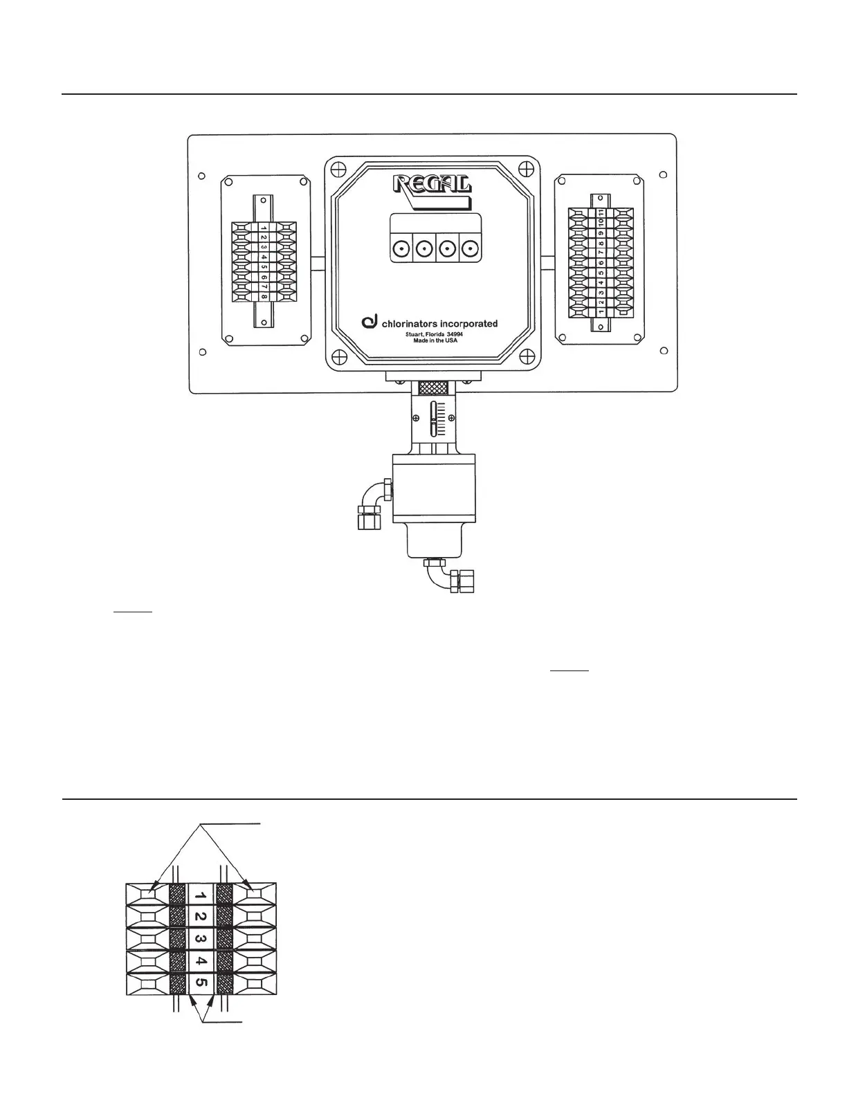
DRAWING NO. 7 — TERMINAL STRIP DESIGNATIONS
Compound Loop Control
Models 7009 and 7010
LEFT SIDE JUNCTION BOX
1 - Flow Signal Input (Pos)
2 - Flow Signal Input (Neg)
3 - Flow Signal Input (Shield)
4 - Analog Output (Pos)
5 - Analog Output (Neg)
6 - Residual Input Signal (Pos)
7 - Residual Input Signal (Neg)
8 - Residual Input Signal (Shield)
NOTE:
Input and Output signals are 4-20mA
RIGHT SIDE JUNCTION BOX
1 - “L”- See Note 1
2 - “N” - See Note 1
3 - Ground - See Note 1
4 - N/O Relay - K1
5 - Com Relay - K1
6 - N/C Relay - K1
7 - N/O Relay - K2
8 - Com Relay - K2
9 - N/C Relay - K2
10 - N/O Relay - K3
11 - Com Relay - K3
NOTE:
1. Terminals 1, 2 and 3 are 120/240
VAC, 50/60Hz, single phase
incoming power supplies.
SMARTVALVE
DRAWING NO. 8 — INSTRUCTIONS FOR USING TERMINAL STRIPS
Located in Junction Boxes of the REGAL SMARTVALVE™
Place the blade of a small screwdriver (such as
the rate valve tool supplied with the REGAL
Chlorinator System) into the slot and tilt the
screwdriver in the direction of the terminal number.
This will open the clamp and allow the wire to be
inserted. Remove the screwdriver and the clamp
will close to hold the wire in place.
Spring-loaded clamps to
hold wires in place
Screwdriver slots used to open wire clamps
25
 Loading...