AQUA24TF/D
Tel +46 (0)31 720 02 00 Fax +46 (0)31 720 02 50
Box 116
428 22 KÅLLERED SWEDEN
1612G APR 02
INSTRUCTIONS INSTRUCTIONS
Start up
1. Check that all wiring is correct.
2. Check that switch 2 is in the correct positions for the installa-
tion on hand.
3. If everything seems to be OK, connect supply voltage and do
those of the following tests that apply to the installation.
Function test: Cascade control.
1. Set function switch 3 and 5 to position A and switches 1 and
4 to position B.
2. Twist the setpoint knob to the clockwise endposition. LED Y1
should light up and the actuator should open the valve.
3. Twist the setpoint knob to the counter clockwise endposition.
LED Y2 should light up and the actuator should close the
valve.
4. Set function switch 4 to position A and switches 1,3 and 5 to
position B.
5. Twist MIN to the clockwise endposition. LED Y1 should light
up and the actuator should open the valve.
6. Twist MIN to the counter clockwise endposition. LED Y2
should light up and the actuator should close the valve.
Function test: Single sensor control.
1. Set function switch 3 and 5 to position A and switches 1 and
4 toposition B.
2. Twist the setpoint knob to the clockwise endposition. LED Y1
should light up and the actuator should open the valve.
3. Twist the setpoint knob to the counter clockwise endposition.
LED Y2 should light up and the actuator should close the
valve.
After completing the test:
Set the function switches in the correct positions for the installa-
tion on hand.
When running cascade control, set the potentiometer MIN to the
desired minimum limiting value for the supply air temperature
and set the cascade factor on potentiometer CF.
17
18
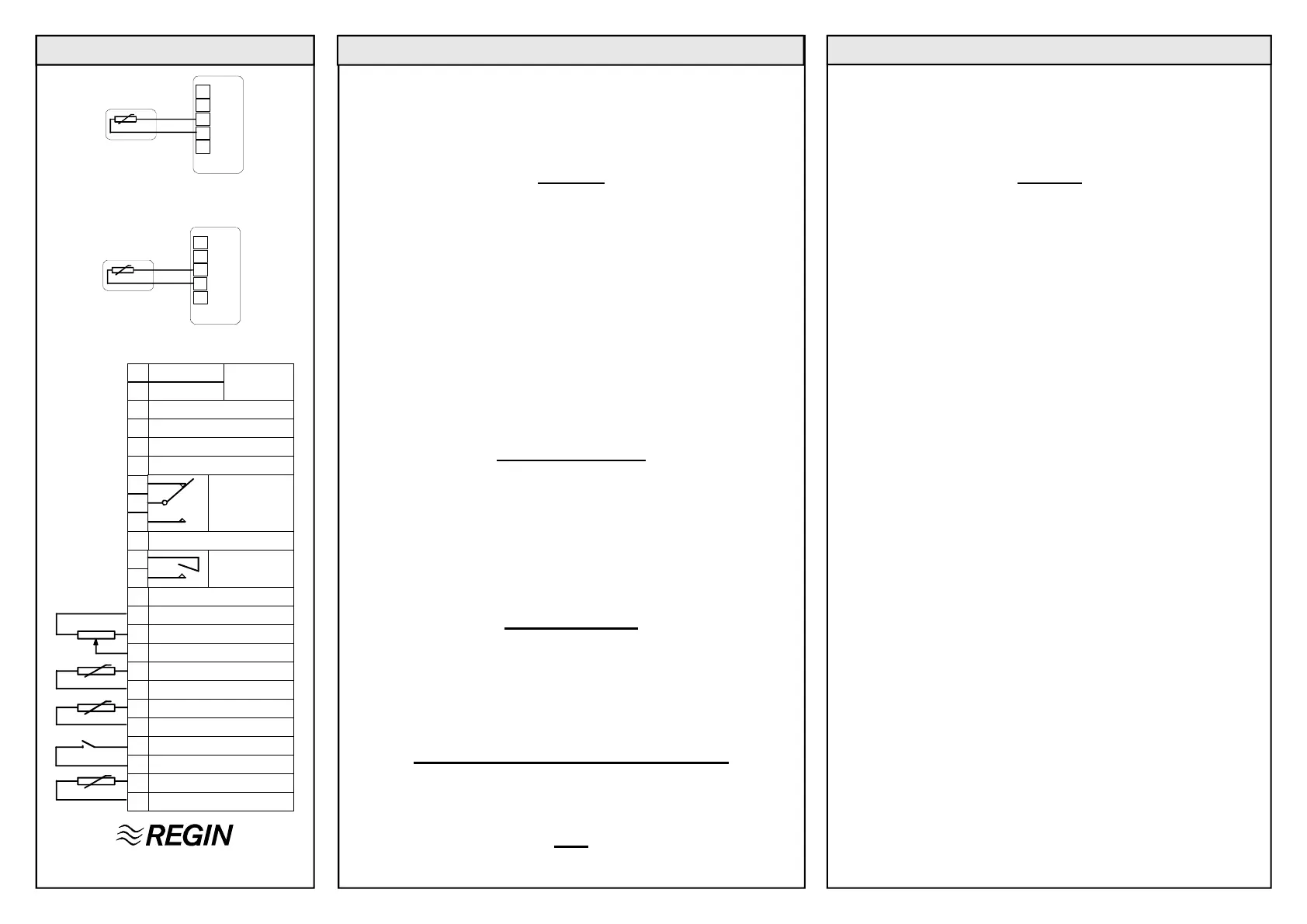
TG-A130
TG-D130
Fig 5
AQUA
19
20
TG-K330
Fig 4
AQUA
Settings
AQUA24TF/D is on delivery set to values suitable as starting values
for balancing the system.
Final settings must be tried out when the system is comissioned.
Factory settings FS in brackets.
Setpoint 0 - 30°C. Setpoint for the main controller.
(FS = 20°C).
CF 1 - 15. Cascade factor. (FS = 1). The value signifies
the immediate change in the duct controller setpoint
for a 1K step change in room temperature.
(Cascade control only).
Min 0 - 30°C. Minimum duct temperature. (FS = 15°C).
(Cascade control only).
N.B. When running single sensor room temperature control (not
cascade control) CF and Min are inactive.
Function switches
1 and 4 in position B
3 and 5 in position A
1 and 4 in position A
3 and 5 in position B
2 in pos. A = Internal
2 in pos. B = External
Wiring diagrams
Fig 1: Main sensor when using the built-in setpoint.
Fig 2: Main sensor and external setpoint TBI-30.
Fig 3: Main sensor and external setpoint when running room
temperature control with room sensor TG-R430.
Fig 4: Limiting sensor when running cascade control.
Fig 5: Frost sensor.
EMC emissions & immunity standards:
This product conforms with the requirements of European EMC
standards CENELEC EN 50081-1 and EN 50082-1 and carries the
CE mark.
LVD
This product conforms with the requirements of European LVD
standards IEC 669-1 and IEC669-2-1.
Single sensor control
Cascade control
Setpoint
1
2
3
4
5
6
7
8
9
10
11
12
13
14
15
16
17
18
19
20
21
22
23
24
Neutral
24V AC in
Not connected
Output common
Output decrease
Output increase
Not connected
SPC 0-10V DC in
Signal neutral
+10V DC out
0-10V DC in
Frost sensor
Signal neutral
Limit sensor
Signal neutral
Fan supervision
Signal neutral
Main sensor
Signal neutral
Alarm relay
24V AC, 2A
Alarm relay
230V AC, 2A
Supply-
voltage
 Loading...