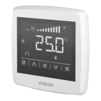
RCF-230D
2
Setpoint
The setpoint displacement is set using the INCREASE and DE-
CREASE buttons. Parameter 24 determines what is shown in the
display. Refer to the parameter list for details. The basic setpoint is
set via parameter 64.
Fan control
The fan can be controlled via RCF-230D with the following modes:
Low speed, Medium speed, High speed, Auto. The current fan speed
in the Auto mode depends on the deviation between the room
temperature and the controlling setpoint.
When using automatic control, ”AUTO” is shown in the display.
The number of fan speed steps can be selected via parameter 30. If
the parameter is set to 1, the rst fan speed step will be used for fan
control.
Via parameter 31, it is possible to set the fan to the lowest speed
level when Auto mode is selected. If this parameter is set to 1, the fan
will run in all operating modes except O and Window (unless mould
protection is active, in which case the fan will run in these modes as
well). Fan kickstart can be utilised. The fan will then run at 100 % for
a set time when starting up (0...10 seconds).
Manual control of the fan speed
By pressing the fan button, you change the fan speed according to
the sequence IàIIàIIIàAUTO. When using manual control, ”MAN” is
shown in the display.
If the fan has been congured not to be aected by the heating or
cooling demand, ”AUTO” will not be shown when pressing the fan
button.
Blocking of manual fan control
When the fan has been congured not to run via parameter 25, it is
possible to also prevent it from being controlled manually. Activation
takes place via parameter 66.
Example: If the fan is congured to run only during cooling demand
and this function has been activated, it will not be controllable during
heating demand.
Indications
The display has the following indications:
HEAT Heating control
COOL Cooling control
The open window symbol is shown if this function has
been congured and a window is open.
OFF The thermostat does not heat or cool
On/O button
By pressing the On/O button, RCF-230D will switch between O mode
and Comfort/Economy mode.
Blocking of buttons
The buttons of the controller can be blocked in order to prevent the set-
tings from being changed by unauthorized individuals. It is possible to
either block only some buttons or, if desired, all of them. Activation takes
place via parameter 65.
The INCREASE and DECREASE button combination will always remain
active in order for the conguration menu to be reachable.
Parameter list
When the thermostat is in Comfort mode or Window mode, dierent
parameter values can be set in a parameter list.
Hold the INCREASE and DECREASE buttons depressed simultaneously
for about 5 seconds until the Service symbol is displayed and then press
the INCREASE button twice.
First the display will show parameter 1. Use the INCREASE and DE-
CREASE buttons to scroll between the parameters and press the On/O
button to select the desired parameter. The parameter number will then
be replaced by the parameter value. The value can be changed using the
INCREASE and DECREASE buttons. If a button is held depressed the
value will start scrolling, rst slowly and then with increasing speed.
To exit the parameter list and go back to the basic display, press the IN-
CREASE button until “EXIT” is shown (one step before parameter 1) and
press the On/O button. You can also exit the parameter list by pressing
down the INCREASE and DECREASE buttons simultaneously.
Parameters
The following parameters can be changed in the parameter list.
Nº = parameter number
FS = factory setting
NO = normally open
NC = normally closed
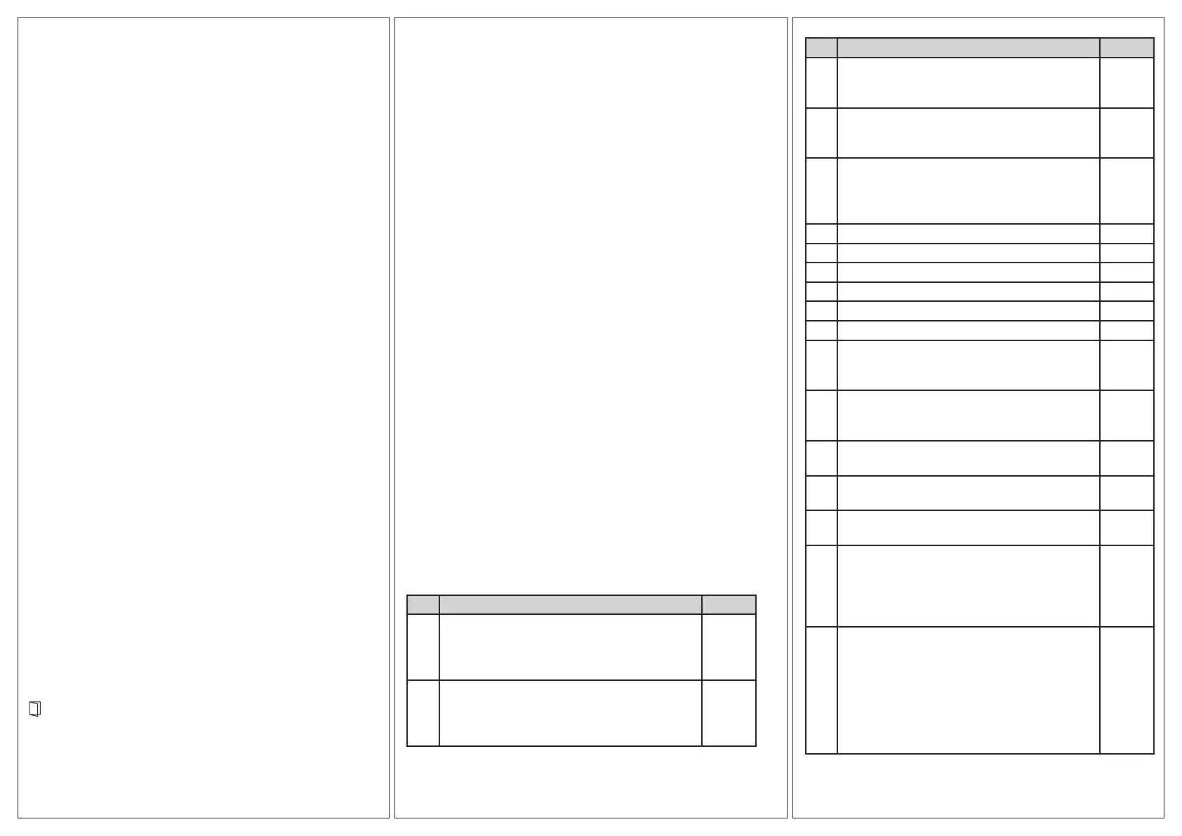
Nº Description FS
1 Control mode:
2=2-pipe system
3=4-pipe system
4=Electric heater (not valid for this model)
3
2 Change-over mode:
0=Heating control, 1=Cooling control, 2=Automatic
change-over depending on analogue temperature
sensor or digital input
2
Nº Description FS
3 Operating mode when activating digital input 1:
0=Economy mode (occupancy detector)
1=O mode (window contact)
0
4 Mould protection:
0=Not active
1=Active (fan never stops)
0
5 Deadband at Comfort mode. If the deadband is
2 K, the heating setpoint is equal to the setpoint
minus 1 and the cooling setpoint is equal to the
setpoint plus 1.
2 K
6 Heating setpoint when unoccupied. 15°C
7 Cooling setpoint when unoccupied. 30°C
8-9 Not used for this model
10 Hysteresis (ΔT) 1 K
11 Switch o timer for Comfort mode 0 min
12 Switch on delay for Comfort mode 0 min
13 Sensor connected to AI1:
0=Internal sensor, 1=External room sensor,
11=Supply air limitation sensor
0
14 Sensor connected to UI1:
0=None, 1=Change-over digital, 2=Change-over
analogue, 3=O mode (open window)
0
15-
21
Not used for this model
22 Time in hours between exercise of heating actua-
tor
23
23 Time in hours between exercise of cooling actua-
tor
23
24 Setpoint or actual value shown in the display:
0=Actual, setpoint when changing the setpoint,
1=Actual value, setpoint adjustment when setpoint
adjustment is altered, 2=Setpoint, 3=Only the
setpoint adjustment
2
25 Conguration of fan control:
0=No control, 1=The fan is controlled by the heat-
ing requirement, 2=The fan is controlled by the
cooling requirement, 3=The fan is controlled by
the heating and cooling requirement
When using an electric heater, this parameter
should only be set to 1 or 3, or the heater may be
overheated.
3
 Loading...