INSTRUCTION
Read this instruction before installation
and wiring of the product
RC-DFO
1
EN
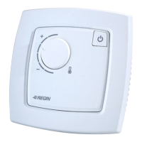
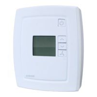
Room controller with fan switch and display
RC-DFO is a room controller from the Regio Mini series, intended to
control heating and cooling in a zone control system. It has a switch
for controlling a three-speed fan (fan coil), and a display. Installation is
directly on the wall or on an electrical connection box. The controller
does not have a communication connection.
Technical data
Supply voltage 18...30 V AC, 50...60 Hz
Internal consumption 2.5 VA
Ambient temperature 0...50°C
Ambient humidity Max 90% RH
Storage temperature -20...+70°C
Display LCD with background illumination
Built-in temperature sensor NTC Type, range 0...50°C, accuracy
+/-0.5°C at 15...30°C
Inputs and outputs Refer to connection illustrations and table
below
Connection terminals Lift type for cable cross-section 2.1 mm
2
Protection class IP20
Material, casing Polycarbonate, PC
Weight 110 g
Dimensions 95 x 95 x 28 mm
INCREASE button
Occupancy button
DECREASE button
FAN button
Installation
Place the controller in a location that has a temperature representative for
the room. A suitable location is approx. 1.6 m above oor level in a place
with unobstructed air circulation.
Remove the frame by depressing the locking tab in the lower edge of the
cover with a screwdriver. See gure 1.
Then prize out the electronics cassette using the four rectangular screwdri-
ver slots and levering against the edge of the bottom plate. See gure 2.
Note: Take care not to damage the electronics when inserting the screw-
driver into the slots.
Figure 1 Figure 2
The bottom plate with terminals has a number of xing hole combina-
tions. Select suitable holes (see gure 3) and screw the bottom plate onto
the wall or connection box, so that the arrows on the bottom plate point
upwards. Do not tighten the screws too hard!
With surface-mounted cabling, break-out suitable holes from the marks in
the plastic.
RC-DFO has digital outputs for control of a 3-speed fan. The relay module
RB3 can be used to handle fans with 230 V AC supply voltage. For more
information, see separate product sheet for RB3.
Figure 3. Bottom plate with mounting alternatives and loca-
tion of terminals (dimensions in mm.)
60
68
Figure 4. Connection diagram for RC-DFO
30
31
32
33
°C
°C
-
24 V AC
40
41
42
43
20
21
22
23
24
10
11
12
13
14
+C
AGnd
-
-
AI1
UI1
DI1
DI2/CI
G
G0
DO1
DO2
DO3
GDO
G0
DO4
UO1
UO2
G0
G
G
G0
Y
G
G0
Y
III
12
13
14
20
RB3
30
31
32
33
L
II
I
-
30
31
32
33
40
41
42
43
20
21
22
23
24
10
11
12
13
14
+C
AGnd
-
-
AI1
UI1
DI1
DI2/CI
G
G0
DO1
DO2
DO3
GDO
G0
DO4
UO1
UO2
Figure 5. Alternative connection for terminals 31, UI1, and terminal
33, DI2/CI, terminal 23, UO1, and terminal 24, UO2.
REGIO RC-DFO
6544E
MAY 19
10 11 12 13 14 20 21 22 23 24
30 31 32 33 40 41 42 43
UP UP