Installation
The Reliable Model B1 Accelerator is quickly attached to var-
ious valves and systems manufactured by Reliable. Table 1
lists the appropriate part numbers as well as technical bulletins
which include installation details.
When installed into the basic trim of a Reliable Model D Dry
Pipe Valve, the Accelerator ½” outlet port should be directly
connected to the intermediate chamber of the dry pipe valve.
In this application, the Model B1 Accelerator directly assists the
clapper of the dry pipe valve to open.
For installations into all other Reliable-manufactured dry sys-
tems such as Models DDX, DDX-LP & EX, the Accelerator
½”outlet port should be vented to the atmosphere. These types
of systems do not utilize differential-type clappers that require
additional air pressure to operate. Instead, these systems uti-
lize a pneumatic actuator to seal a push rod chamber and me-
chanically latch a valve closed. In this instance, the Model B1
Accelerator speeds up the purging of the air side of the Model
LP Actuator which in turn vents the push-rod chamber pressure
of the main fire control valve causing its clapper to open and fill
the system piping with water.
Note: The Model B1 Accelerator may be capable of hastening
the operation of non-Reliable manufactured valves, however, it
has only been tested and approved with Reliable valves.
System Requirements
NFPA (National Fire Protection Association) 13 titled “Installation
of Sprinkler Systems”, specifies that Accelerators (quick-open-
ing devices) are required on dry systems having capacities of
more than 500 gallons. However, exceptions permit the omis-
sion of quick-opening devices for larger systems when water
can be delivered to the inspector’s test connection in less than
60 seconds.
• Reliable’s Accelerator is UL Listed for system volumes to
1500 gallons. This capability is also approved by FM.
• System pneumatic pressure must be maintained at a mini-
mum of 15 psi in order for the Accelerator to operate.
It must be cautioned that accelerator operation and water de-
livery at the inspectors test connection does not occur at the
same time. There is a delay while the air is being expelled
through the inspectors test connection ahead of the water. This
time delay depends on the piping configuration system size,
available water supply and other factors which are beyond the
control of the accelerator.
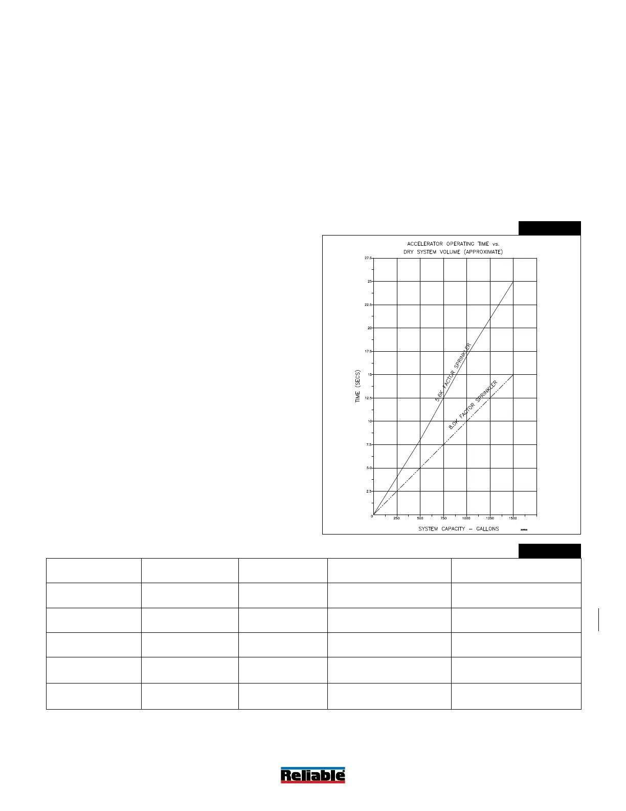
Figure 2 provides an approximate graph of actual Accelera-
tor operating time versus system size when one sprinkler head
opens. The time of operation of the Accelerator is relatively
unaffected by inlet pressures so the graph applies for all nor-
mal dry system pressures from 25 psi to 50 psi (1.7 bar to 3.4
bar). As described above, water delivery time will significantly
exceed the accelerator operating times shown in Figure 2.
Model B-1 Accelerator Operating Time
Figure 2
Accelerator Compatibility
Table A
Valve System Type Technical Bulletin Accelerator Part Numbers Trim Kit Part Number
Model D Dry Pipe 350 6301000300 6516000002
Model EX Dry Pipe 359 6516000013 (Included)
Model DDX-LP Dry Pipe 338 6501200019 (Included)
Model DDX Type F
Double Interlock
Preaction
751 6501200019 (Included)
Model DDX Type PL
Double Interlock
Preaction
752 6501200019 (Included)
Bulletin 323
May 2019
Page 3 of 7
www.reliablesprinkler.com
 Loading...