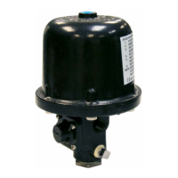
Resetting Procedure For Model LDX, DDX, EX
Dry Systems & Model DDX Type F Preaction
Systems
Note: These steps must be followed each and every time the
system has operated or is tested.
1. Isolate the Accelerator by closing the inlet valve.
2. Close the air and water supply valves to the deluge valve.
Drain and reset the system in accordance with the manu-
facturers instructions.
3. Close the main water supply control valve and open the
system main drain. This step serves to prevent accidental
operation of the system while resetting the Accelerator.
4. Remove the 1/4” body drain plug from the lower section of
the Accelerator.
5. Remove the 1/4” top chamber drain plug. If water is pres-
ent in the top chamber, disassemble the Accelerator, clean
and dry the top and middle chambers and diaphragm as-
sembly using a clean lint free cloth. Reassemble the Ac-
celerator. Replace the top chamber drain plug using new
thread sealant.
6. Carefully remove the Accelo-Check Body, and gently lift the
Accelo-Check Diaphragm Assembly to verify venting of the
middle chamber. Carefully reinstall these parts.
7. Partially open the Accelerator inlet valve, gently purging
any water which may be in the trim lines. Close the inlet
valve and replace the 1/4” body drain plug on the lower
section of the Accelerator.
8. Pressurize the Accelerator by opening the inlet valve. The
top chamber pressure of the Accelerator should equal the
system pressure.
9. Slightly open the main water supply control valve. Close the
main drain valve when water flows, then fully open the main
supply valve. The system is now ready for service.
Caution
The presence of water in the Accelerator may cause premature
operation. Therefore, it is imperative that after system operation,
the Accelerator be inspected for any signs of water and that the
Accelerator trim lines are purged prior to completing the Ac-
celerator reset procedure. In addition, after system set–up, the
prime water level must not exceed the dry pipe valve’s prime
level (if applicable).
Recommended Periodic Inspections
The following inspections should be performed on the Model B1
Accelerator on a weekly basis.
1. Check that the correct system air pressure is being main-
tained
2. Verify that Accelerator top chamber pressure and system
air pressure are equal.
3. Verify that the valves located on both the Accelerator’s inlet
and outlet lines are in the open position. A valve located
on the Accelerator outlet port should only be present if the
Accelerator is connected into a dry pipe valve intermedi-
ate chamber. Otherwise, the Accelerator outlet port should
vent to the atmosphere.
4. Check that the prime water level is correct (if applicable).
Test
The following Accelerator tests should be performed semi–
annually or whenever the Accelerator has been disassembled.
A) Accelerator test without operating the dry pipe valve.
1. Isolate the Accelerator by closing the valves located on
its inlet and/or outlet ports.
2. Loosen the 1/4” (lower) body drain plug in order to de-
cay the pressure at the inlet of the Accelerator. This will
simulate a system decay as when one or more sprin-
klers open. The Accelerator should operate.
3. Reset the Accelerator following the instructions de-
scribed in the “Resetting Procedure” sections of this
bulletin.
B) Sensitivity Test (Model D Dry Pipe Valves only)
1. Close the main water supply control valve.
2. Bleed the system air pressure at a rate of 1 psi per min-
ute.
3. After ten minutes (the air pressure should have de-
cayed 10 psi) the Accelerator should not have tripped.
4. Restore the system air pressure and reopen the main
water supply control valve.
Resetting Procedure For Model D Dry Pipe
Valve Systems (refer to Fig. 1)
Note: These steps must be followed each and every time the
system has operated or is tested.
1. Isolate the Accelerator by closing the inlet and outlet
valves.
2. Close the air supply and main water supply valves to the
dry pipe valve. Drain and fully reset the dry pipe valve in
accordance with the manufacturers instructions.
3. Close the main water supply control valve and open the
system main drain. This step serves to prevent accidental
operation of the system while resetting the Accelerator.
4. Remove the 1/2” drain plugs on the inlet and outlet piping.
5. Remove the 1/4” body drain plug from the lower section of
the Accelerator.
6. Remove the 1/4” top chamber drain plug. If water is
present in the top chamber, disassemble the Accelerator,
clean and dry the top and middle chambers and dia-
phragm assembly using a clean lint free cloth. Reassem-
ble the Accelerator. Replace the top chamber drain plug
using new thread sealant.
7. Carefully remove the Accelo-Check Body and gently lift
the Accelo-Check Diaphragm Assembly to verify venting
of the middle chamber. Carefully reinstall these parts.
8. Partially open the Accelerator inlet valve, gently purging
any water which may be in the trim lines. Close the inlet
valve.
9. Replace the 1/2” drain plugs on the inlet and outlet piping.
10. Partially open Valve A and gently purge the Accelerator.
Close Valve A and replace the 1/4” body drain plug on the
lower section of the Accelerator.
11. Open the Accelerator outlet valve.
12. Pressurize the Accelerator by opening the inlet valve.
When properly set, the top chamber pressure of the Ac-
celerator should equal the system pressure.
13. Slightly open the main water supply control valve. Slowly
close the main drain valve when water flows, then fully
open the main supply valve. The system is now ready for
service.
Bulletin 323
May 2019
Page 4 of 7
www.reliablesprinkler.com

 Loading...