7
ENGLISH
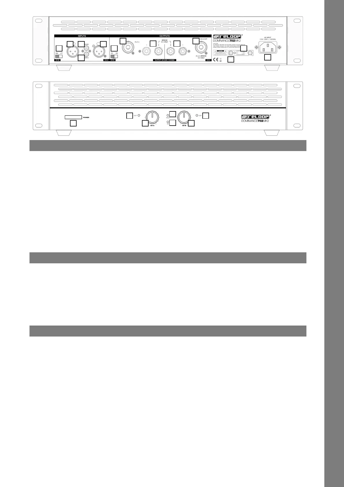
DESIGNATION
1. ON/OFF Switch
2. Volume Control Channel A
3. Volume Control Channel B
4. Power Supply LED
5. Protective Circuit LED
6. Peak LEDs
7. Mains Connection
8. Fuse
9. Voltage Selector
10. Ground/Lift Switch
11. Line In Channel A (XLR)
12. Line In Channel B (XLR)
13. Line In Channel A (RCA)
14. Line In Channel B (RCA)
15. Loudspeaker Connection Channel A (terminal screws)
16. Loudspeaker Connection Channel B (terminal screws)
17. Loudspeaker Connection Channel A (PA Pro)
18. Loudspeaker Connecton Channel B (PA Pro)
19. Mode-Selcting Switch
INSTALLATION
- This nal amplier is designed to be tted into a 19“ rack. Secure the nal amplier with four M6 screws to the rack.
- Select a location with sufcient circulation of air. Permanent overheating can damage the nal amplier.
- When installing into the rack please ensure that warm air can escape the rack and that there is adequate distance between the individual devices.
The rack case should be equipped with an aerator.
- The nal amplier is equipped with additional fans that provide adequate cooling. Make sure the device is placed in a position that allows suf-
cient air ventilation.
- Please proceed cautiously when installing the nal amplier into the rack. Install heavier equipment to the lower part of the rack. The front plate
alone is insufcient to secure the nal amplier. A balanced fastening to the oor and side rails must be guaranteed.
- If racks are transported or are used for mobile acoustics the rear brackets of the equipment should additionally be attached to the ground and
side rails of the rack. This prevents the nal amplier from shifting during transport as the front plate alone can not absorb accelerating powers
that arise when on the road.
CONNECTIONS
1. Stereo Mode with 2 Speakers
First connect your speakers. If your speakers feature connectors for open wire cords, connect the left speaker to Loudspeaker Connection Chan-
nel A (terminal screws) -15- and the right speaker to Loudspeaker Connection Channel B (terminal screws) -16-. Connect the „+“ pole lead of the
respective connecting cable to the „+“ pole connecting terminal of the respective channel and the „-“ pole lead of the respective connecting cable
to the „-“ pole connecting terminal of the respective channel. If your speakers feature connections for PA Speaker Cord Pro, connect your left
speaker to Loudspeaker Connection Channel A (PA Pro) -17- and your right speaker to Loudspeaker Connection Channel B (PA Pro) -18-. The Mode-
Selecting Switch -19- has to be set to “STE” (stereo).
CAUTION!
The loudspeakers’ resistance during this operation mode must not fall below 4 Ohm.
2. Mono-Bridged Mode with 1 Speaker
Set the Mode-Selecting Switch -19- to “BRI” (bridged). If your speaker features a connector for open wire cords, connect the “+” pole lead of the
connecting cable to the “+” pole connecting-terminal of channel A -15- and the “-” pole lead of the connecting cable to the “-” pole connecting-
terminal of channel B -16-.
NOTE!
If you use PA Speaker Pro cords, make sure to use 4-pole connecting-plugs with a conguration of 1+ & 2-.
CAUTION!
The loudspeakers’ resistance during this operation mode must not fall below 8 Ohm. The Mode-Selcting Switch -19- must not be switched
during operation.
NOTE!
In mono bridged mode, it is necessary to adjust volume via both volume dials -2- & -3-.
1
12
2
13
3
14
4
15
5
16
6 6
17
7
18
8
19
9
10
11
IM_Dominance Serie MK2_eng.indd 7 21.02.2019 10:03:01
 Loading...