16
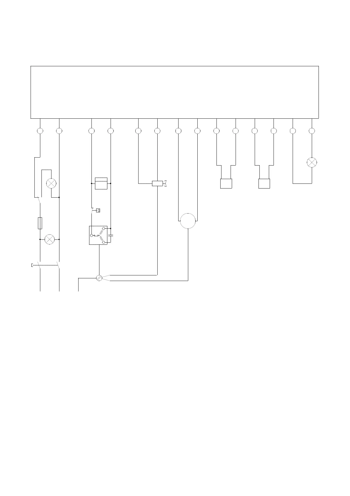
Wiring Diagram AMT 60-E
C1 = Capacitor
F1 = Main fuse
H1 = Control lamp, yellow (tank full)
H2 = Control lamp, green (operation)
H3 = Control lamp, red (fault)
M1 = Compressor
M2 = Fan motor
OP = Overload protection, compressor
P1 = Running hour meter
R1 = Temperature sensor (red)
R2 = Temperature sensor (blue)
S1 = Main switch
S2 = Micro switch, water container
Y1 = Solenoid valve
MAINS COMPR. VALVE FAN COND.
NTC
EVAP.
NTC
FAIL
LAMP
1 2 3 4 5 6 7 8 20 21 22 23 24 25
CONTROL BOARD
H1
yellow
H2
green
S1
S2
5 2
4 1
C
S
R
h
P1
L1 N
L1 N PE
230V/1~ 50Hz
M1
Y1
M
1~
R1
red
R2
blue
H3
red
We reserve the right to make modifications in dimensions and construction in the interests of technical progress.
C1
OP
F1
8,2 A
M2
L1 N
2 4
1