21
The following electrical connections must be made:
◊ Connecting the power supply
◊ Connecting the cable remote control if applicable
Please follow the instructions below to install the electri-
cal connections:
◊ The inner units function independently of the chiller.
An electrical control line is hence not necessary.
◊ The electrical connections are to be performed as
fixed connections in accordance with the relevant
regulations.
◊ An all-polo separating switch is to be installed in the
power line in front of the unit.
◊ The power line must be insulated adequately by the
customer and the line drop may not fall below the
permissible values.
◊ Make sure that the electrical system is suitable to
supply the required operating current for operating
the unit and any other units that are already in opera-
tion.
◊ Prior to installation, if connections are made to exist-
ing system parts, you must check that the line has
the right dimensions for unit consumption.
◊ The units must always be connected with low-ohm
protection conductors with sufficient dimensions. In
certain circumstances, the module must be grounded
as a measure to protect against lightning in several
places (especially when plastic pipes are used).
Terminal
strip
Normal status
Input /
Output
Function Connections
01 – 02
ST 1 Incoming water - Sensor PTC - input
03 – 04
ST 2 Outgoing water – Sensor PTC - input
05 – 06
ST 5 Condenser – Sensor PTC - input
07 – 08
closed AT 1 High pressure switch Neutral contact
09 – 10
closed AT 3 Low pressure switch Neutral contact
11 – 12
closed AT 5 Not in use Neutral contact
13 – 14
12 V ~ Tr Current supply 12 V ~, 50 Hz
15 – 16
Closed when pump is in operation AT 9 Differential pressure monitor Neutral contact
15 – 17
AT 7 Heating-cooling removed Neutral contact
15 – 18
closed AT 10 On Off, remote control contact for heating pump Neutral contact
19 – 20
RL 1 Global shut-off Max. 48 V ~, 200 mA
22 – 23
RL 2 Defrost heating / Boiler signal 230 V ~, 50 Hz, 4,0 A
22 – 24
RL 4 Compressor 230 V ~, 50 Hz, 0,4 A
22 – 25
RL 8 Circulation valve (heating pump only) 230 V ~, 50 Hz, 0,4 A,
21 – 22
RL 10 Pump switch contact 230 V ~, 50 Hz, 4,0 A
42 – 43
TK 1 Fan regulation - output Phase regulation
Description of the CH-DIN inputs and outputs
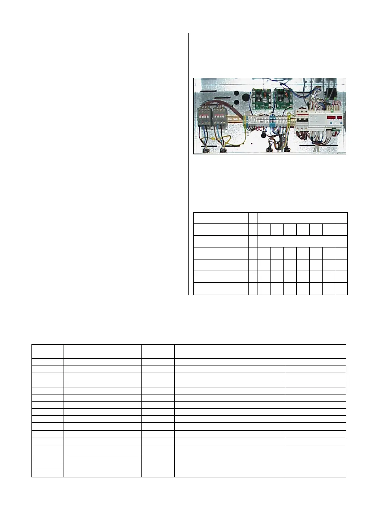
All electrical connections such as power input, cable re-
mote control, etc., are to be made in the switch box of
the unit. The lines to be laid must be guided through the
appropriate cable penetrations on the back of the unit
into the housing.
All units require a three-phase alternating current con-
nection. The power line is to be guided through the L1,
L2, L3, N and PE terminal strips.
The line dimensions are based on the local conditions.
The connection capacity of units can be found in the ta-
ble below:
Type
RKW INOX
1000 1600 2600 3600 4500 8000 9800
Electrical connection
400 V /3~, N. PE / 50 Hz
Power consumption kW
4.4 7.1 11.2 15.7 19.4 36.0 45.2
Cur. Consumption max. A
8 12.8 18.8 26.3 32.6 58.5 73.5
Start-up current A
49 101 167 2x90 2x120 2x116 2x127
Fuse protection
customer-side
A
20 20 25 35 50 80 100
Electrical Connection
G
Warning! The units are equipped with a phase-sequencer relay that prevents the unit from operating if the ro-
tational direction of the electrical connection is wrong. If the chiller remains neutral (i.e. no current) when be-
ing put into operation, the rotational field must be switched.
G
Electrical installations may only be performed by
authorised service personnel. Prior to performing
any work on the unit, it must be unplugged from
the power supply.
 Loading...