EasyManuals Logo

Remootio 3 User Manual

Remootio 3
20 pages
To Next Page IconTo Next Page
To Previous Page IconTo Previous Page
Page #3 background imageLoading...
Page #3 background image
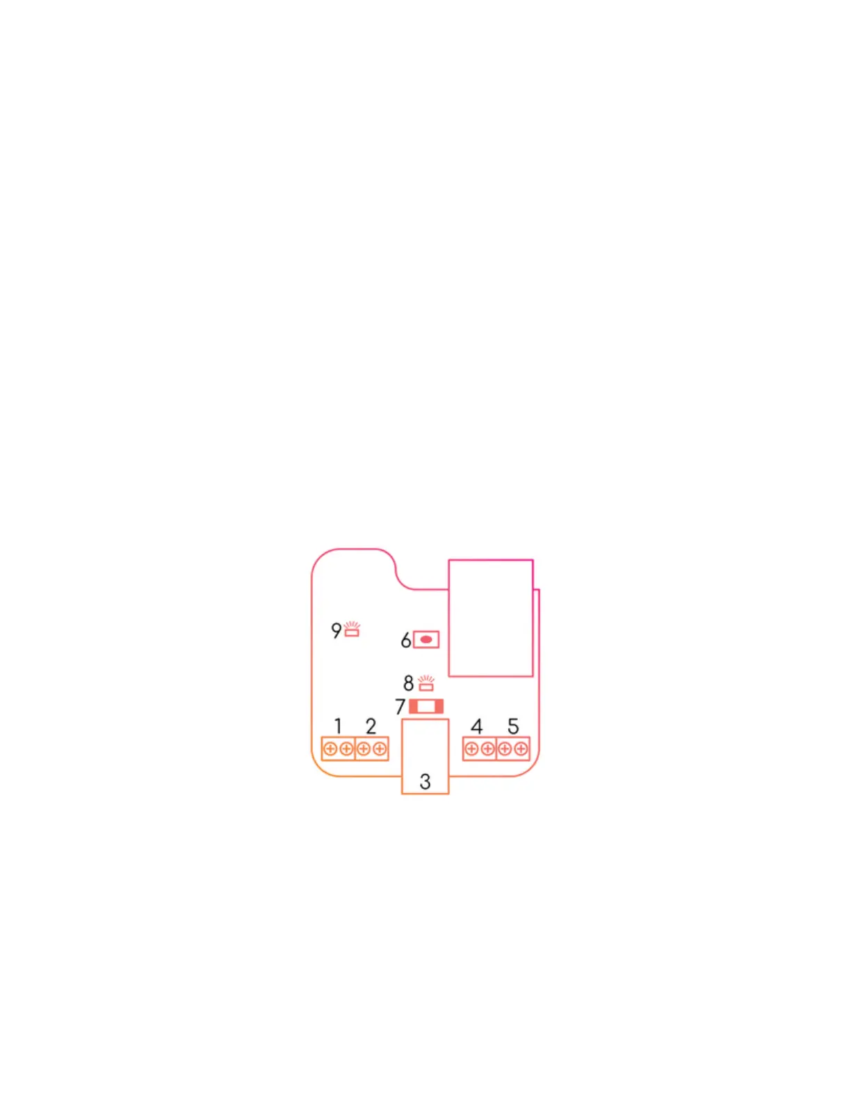
Remootio 3 pinout diagram:
1. control output 1 (normally open relay)
2. control output 2
(normally open relay)
3. power input
5-32VDC | 12-24VAC
min. 100mA
4. add-on input 1
(e.g. sensor input)
5. add-on input 2
(e.g. doorbell button input)
6. reset button
7. fuse
8. feedback LED
9. power OK LED
Step 2 - Wiring the control output
Connect the control output of the Remootio unit to the appropriate input terminals of your gate
or garage door. In some cases, there is only one input pair (single input) and in other cases
there are two input pairs (dual input) on the control board that has to be triggered to open or
close the gate or garage door.

Questions and Answers:

Question and Answer IconNeed help?

Do you have a question about the Remootio 3 and is the answer not in the manual?

Remootio 3 Specifications

General IconGeneral
ConnectivityWi-Fi, Bluetooth
User CapacityUnlimited users
IFTTT IntegrationYes
Operating Voltage12-24V DC
Power Supply12-24V DC
App ControliOS and Android
Voice ControlAmazon Alexa, Google Assistant
Operating Temperature-20°C to +50°C (-4°F to +122°F)
Relay Outputs2 relay outputs
Operating RangeUp to 100m (328ft) in open space for Bluetooth