2. Preparations for use
Note: Weights above 35 kg (77 lbs) need to be carried by two people,
tool set to be carried separately. Pay attention that during transporta-
tion and setting up of the machine, with the stand or without it, the cen-
ter of gravity is high, i.e. top heavy.
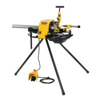
2.1. Set up of Tornado 2000, 2010, 2020 (Fig.1–3)
Loosen wing screw (1). Remove tool holder (2). Position the drive unit
vertically on both guiding arms (3 + 4) and insert the 3 legs into the
gearbox casing until they snap in (fig. 1). Take the machine at the gear-
box casing (not at the legs), and put it upright onto the legs (fig. 2).
The machine can also be mounted on a bench and be attached with
screws. 3 threaded holes are provided on the machine base. Through
the attached pattern 3 holes have to be drilled (12 mm Ø drill) through
the bench. Then fix the machine with 3 screws (M 10) from under-
neath.
Push the tool holder on the guiding arms. Push the pressing lever (5)
from behind through the shackle on the tool holder and fix the lockin
ring (6) on the rear guiding arm in such a way that the wing screw is
positioned backwards leaving the snap ring groove free. Push the
handle (7) on the pressing lever.
Suspend the tray on both screws attached below the gearbox casing
and push it sidewards right into the slots. Suspend the tray onto the
snap ring groove in the rear guiding arm (4). Push the clamping ring
of the pressing lever right to the suspension of the tray and fix it.
Put the hose with the suction filter into the tray and push the other end
of the hose on the nipple on the back of the tool holder. Fill with 2 ltrs.
of thread cutting oil. Set in the chip tray from the rear.
Never keep running the machine without thread cutting oil.
Put the guide bolt of the die head (8) into the boring of the tool holder
and push the die head with axial pressure on the guide bolt and tur-
ning movements right to the stop. For transport, the foot switch can
be hooked to the screw above the rear clamping chuck (fig. 3).
Set up of Magnum 2000 T, 2010 T, 2020 T, 4000 T, 4010 T, 4020 T
(Fig. 8)
Fasten the machine on a workbench or wheel stand (accessory) with
the 3 delivered screws. For transport the machine can be lifted at the
guide arms in front and at rear with a pipe which is clamped into the
hammer and guide chuck. For transport on the wheel stand use pie-
ces of pipe Ø
3
/
4
” with length of about 60 cm and fasten the wing screws.
If the machine has not to be transported, remove the two wheels.
Fill with 5 Itrs. of thread cutting oil. Never run the machine without
thread cutting oil.
2.2. Set up of Tornado 2000T, 2010T, 2020T (Fig. 7 + 8)
Fasten the machine on a workbench or wheel stand (accessory) with
the 3 delivered screws. For transport the machine can be lifted at the
front grip pockets of the basin an in rear at the motor or at the mate-
rial support fixture. For transport on the wheel stand use pieces of pipe
Ø
3
/
4
” with length of about 60 cm and fasten the wing screws. If the
machine has not to be transported, remove the two wheels. Fill with
5 Itrs. of thread cutting oil. Never run the machine without thread cut-
ting oil.
Set up of Magnum 2000 T-L, 2010 T-L, 2020 T-L (Fig. 8)
Fasten the machine on a workbench or stand (accessory) with the 4
delivered screws. For transport the machine can be lifted at the guide
arms in front and at rear with a pipe which is clamped into the ham-
mer and guide chuck. Slide clamping ring (10) with wing screw onto
the rear guide arm so that the groove remains empty. Put the pan onto
the two bolts which are located at the lower end of the gear housing
and into the groove at the rear guide arm. Slide clamping ring (10)
against the support ring of the pan and tighten it. Hang the hose with
eng eng
1.3. Electrical data
Tornado 2000, Magnum 2000 / 4000 230 V, 1~; 50-60 Hz; 1700 W input, 1200 W output; 8.3 A;
Fuse (mains) 16 A (B). Intermittent service 2.5 / 10 min.
110 V; 1~; 50-60 Hz; 1700 W input, 1200 W output; 16.5 A;
Fuse (mains) 30 A (B). Intermittent service 2.5 / 10 min.
Tornado 2010, Magnum 2010 / 4010 230 V, 1~; 50 Hz; 2100 W input, 1400 W output; 10 A;
Fuse (mains) 10 A (B). Intermittent service 7 / 10 min.
Tornado 2020, Magnum 2020 / 4020 400 V; 3~; 50 Hz; 2000 W input, 1500 W output; 5 A;
Fuse (mains) 10 A (B). Intermittent service 7 / 10 min.
1.4. Dimensions (L x W x H)
Tornado 2000 730 x 435 x 280 mm
Tornado 2010 / 2020 730 x 435 x 280 mm
Magnum 2000 870 x 580 x 495 mm
Magnum 2010 / 2020 825 x 580 x 495 mm
Magnum 4000 915 x 580 x 495 mm
Magnum 4010 / 4020 870 x 580 x 495 mm
1.5. Weight in kg
Machine Tools Standard accessories
Tornado 2000 31 12 7
Tornado 2010 43 12 7
Tornado 2020 43 12 7
Machine Machine Tools Tools Wheel
1
/
4
– 2” 2
1
/
2
– 4”
1
/
4
– 2” 2
1
/
2
– 4” stand
Magnum 2000 75 12 16
Magnum 2010 87 12 16
Magnum 2020 87 12 16
Magnum 4000 96 12 24 16
Magnum 4010 108 12 24 16
Magnum 4020 108 12 24 16
1.6. Noise data
Workstation-related emission data
Tornado 2000, Magnum 2000 / 4000 83 dB (A)
Tornado 2010, Magnum 2010 / 4010 75 dB (A)
Tornado 2020 72 dB (A)
Magnum 2020 / 4020 74 dB (A)
1.7. Vibrations (all types)
Weighted effective value of acceleration 2,5 m/s
2
 Loading...