EasyManuals Logo
Home>Renesas>Computer Hardware>RL78/F24

Renesas RL78/F24 User Manual

Renesas RL78/F24
58 pages
To Next Page IconTo Next Page
To Previous Page IconTo Previous Page
Page #19 background imageLoading...
Page #19 background image
E1/E20/E2/E2 Lite Additional Document 2. Designing the User System
R20UT1994EJ0900 Rev.9.00 Page
19
of 58
Jan.20.22
2.4 Recommended Circuits between the Connector and the MCU
This section shows recommended circuits for connection between the connector and the MCU when the
E1/E20/E2/E2 Lite is in use. For processing of signals, refer to section 2.5, Notes on Connection.
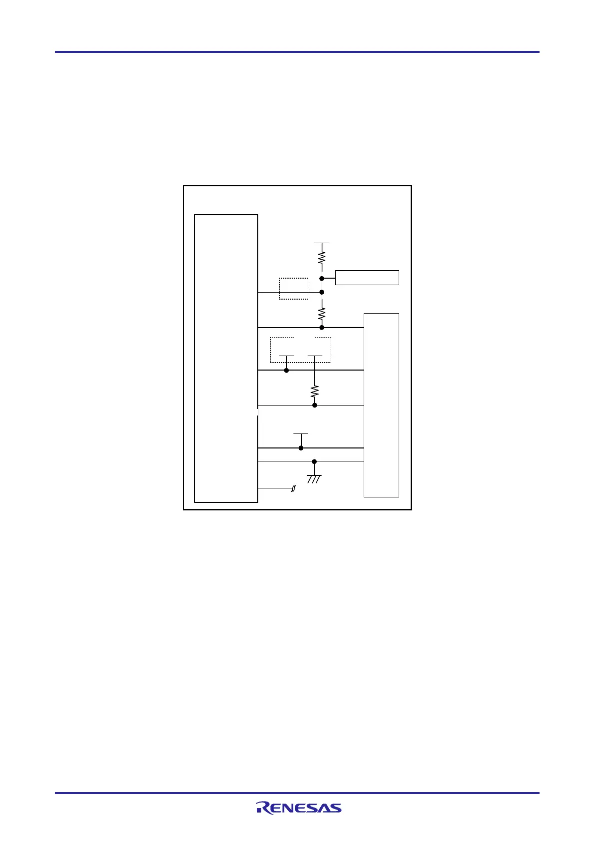
2.4.1 Connection between the 14-Pin Connector and the RL78 Family MCUs in General
Figure 2-5 shows a recommended circuit for connection between the 14-pin connector and the RL78 family
MCUs in general.
MCU
8
VSS
14-pin 2.54-mm pitch
connector
VDD
9 EVDD
2,12,14
5
TOOL0
TOOL0
EMVDD
VDD
VSS
10 kW
1 kW
Reset circuit
6
10,13
VDD
RESET_IN
RESET_OUT
RESET#
1 kW
1,3,4,7,11
R.F.U
Note 1
Note 3
Note 3
Driving power supply
for TOOL0
VDD
Note 4
Note 5
Note 6
Note 3, Note 7, Note 8
Note 5
Note 2
Figure 2-5 Example of Connection between the 14-Pin Connector and the RL78 Family MCUs in
General

Table of Contents

Questions and Answers:

Question and Answer IconNeed help?

Do you have a question about the Renesas RL78/F24 and is the answer not in the manual?

Renesas RL78/F24 Specifications

General IconGeneral
BrandRenesas
ModelRL78/F24
CategoryComputer Hardware
LanguageEnglish

Related product manuals