E1/E20/E2/E2 Lite Additional Document 2. Designing the User System
R20UT1994EJ0900 Rev.9.00 Page
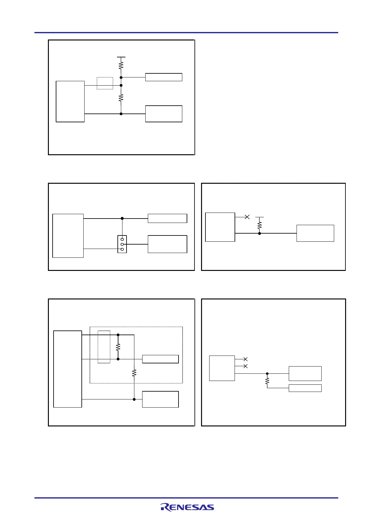
14-pin
2.54-mm pitch
connector
10 kW
1 kW
Reset circuit
6
10,13
VDD
RESET_IN
RESET_OUT
Note 1
R1
R2
MCU
RESET#
<Connection Example of RESET for RL78 Family MCUs in General>
(Recommended Circuit)
Note 1: The emulator operates for flash programming by the programming software
whether this pin is connected or not.
Note 2
Note 2
Note 2: Make the resistance of R2 at least ten times that of R1, and at least 10 kΩ.
Pulling up of R1 is unnecessary if the high level is being output by the C-MOS buffer in
the reset circuit.
Figure 2-9 Connection Example 1 of RESET#
(RL78 Family MCUs in General)
14-pin
2.54-mm pitch
connector
MCU
Reset circuit
6
10,13
RESET_IN
RESET_OUT
RESET#
<Connection Example of RESET for RL78 Family MCUs in General>
(A jumper is used to switch connection to the E1/E20/E2 Lite.)
A
B
C
When E1/E20/E2/E2 Lite is connected: B-C shorted
When E1/E20/E2/E2 Lite is not connected: A-B shorted
14-pin
2.54-mm pitch
connector
MCU
6
10,13
RESET_IN
RESET_OUT RESET#
VDD
<Connection Example of RESET for RL78 Family MCUs in General>
(The power-on reset circuit is the only reset circuit on the user system.)
1 k to 10 kW
Figure 2-10 Connection Example 2 of RESET#
(RL78 Family MCUs in General)
Figure 2-11 Connection Example 3 of RESET#
(RL78 Family MCUs in General)
470 to 510 W
1 kW
Reset circuit
6
10,13
RESET_IN
RESET_OUT
4
RSTPU
Note 1
14-pin
2.54-mm pitch
connector
MCU
RESET#
<Connection Example of RESET when the Target MCU is the RL78/G11, 20- and 24-Pin
Versions of the RL78/G12 or an RL78/I1C with the Battery Backup Function not in Use>
(Recommended Circuit)
Note 1: The emulator operates for flash programming by the programming software
whether this pin is connected or not.
Note 2
Note 2: Connection is unnecessary when there is no reset circuit on the user system.
14-pin
2.54-mm pitch
connector
MCU
6
10,13
RESET_IN
RESET_OUT RESET#
4
RSTPU
External circuit
1 kW
<Connection Example of RESET for the RL78/G11 and 20- and 24-Pin Versions of the RL78/G12>
(when using a function which is multiplexed with RESET#)
Figure 2-12 Connection Example 1 of RESET#
(when the Target MCU is the RL78/G11, 20- and 24-
Pin Versions of the RL78/G12 or an RL78/I1C with the
Battery Backup Function not in Use)
Figure 2-13 Connection Example 2 of RESET#
(the RL78/G11 and 20- and 24-Pin Versions of the
RL78/G12)

 Loading...


