07
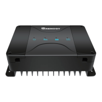
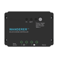
Identification of Parts
Installation
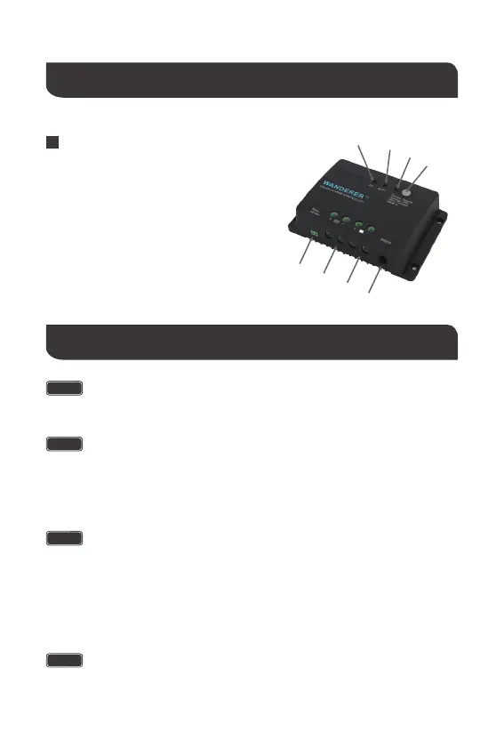
Key Parts
1. Battery Select Button
2. Battery Type Indicator
3. Battery Indicator
4. PV Indicator
5. Remote Temperature Sensor Port (optional accessory)
6. PV Terminals
7. Battery Terminals
8. RS-232 Port (optional accessory)
NOTE
Mark Holes
Drill Holes
Secure the charge controller.
Connect battery terminal wires to the charge controller FIRST then connect the solar panel(s) to
the charge controller. NEVER connect solar panel to charge controller before the battery.
Do not over-torque or over tighten the screw terminals. This could potentially break the piece
that holds the wire to the charge controller.
Refer to the technical specifications for max wire sizes on the controller and for the maximum
amperage going through wires.
Never install the controller in a sealed enclosure with flooded batteries. Gas can
accumulate and there is a risk of explosion.
CAUTION
WARNING
WARNING
Mounting Recommendations:
Choose Mounting Location—place the controller on a vertical surface protected
from direct sunlight, high temperatures, and water. Make sure there is good ventilation.
1.
Check for Clearance—
verify that there is sufficient room to run wires, as well as clearance
above and below the controller for ventilation. The clearance should be at least 6 inches (150mm).
2.
3.
4.
5.
The Wanderer is not equipped with screws for wall mounting.
①
②
③
④
⑤
⑥
⑦
⑧
 Loading...