
T
Teresa GomezAug 3, 2025
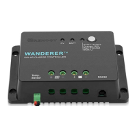
What to do if my Renogy Controller battery is low-voltage?
- Bbrian95Aug 3, 2025
If the battery is low-voltage, use a multimeter to verify the rated battery voltage. Disconnect any loads connected to the battery to allow it to charge.