

J
Jerry McdowellJul 28, 2025
What to do if the Renogy Controller load indicator is flashing white?
- JJessica LynchJul 28, 2025
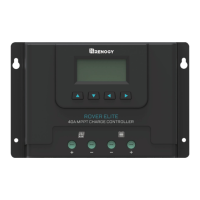
If the load indicator on your Renogy Controller is flashing white, several issues could be the cause. First, use a multimeter to check the battery voltage to ensure it's not exceeding 32 volts. The load circuit on the controller might be shorted or overloaded; ensure the device connected is properly connected and doesn't exceed 20A (DC). Also, check the LCD for any error codes.