EasyManuals Logo

Renogy ROVER Series User Manual

Renogy ROVER Series
36 pages
To Next Page IconTo Next Page
To Previous Page IconTo Previous Page
Page #10 background imageLoading...
Page #10 background image
Key Parts
09
Identification of Parts
1. Charging Indicator
2. Battery Indicator
3. Load Indicator
4. Abnormality Indicator
5. LCD Screen
6. Operating Keys
7. Installation Hole
8. Solar panel “+” Interface
9. Solar panel “-” Interface
10. Battery “-” Interface
11. Load “-” Interface
12. Battery “+” Interface
13. Load “+” Interface
14. External Temperature Sampling Interface
15. Battery Voltage Compensation Interface
16. Controller Parallel Port
17. RS232 Communication Interface
18. RS485 Communication Interface

Other manuals for Renogy ROVER Series

Questions and Answers:

Question and Answer IconNeed help?

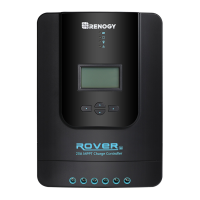
Do you have a question about the Renogy ROVER Series and is the answer not in the manual?

Renogy ROVER Series Specifications

General IconGeneral
Temperature Compensation-3mV/°C/2V(Default)
TypeMPPT
Nominal System Voltage12V/24V Auto
Rated Charge Current20A, 30A, 40A, 60A
Max PV Input Voltage100V (20A/30A), 150V (40A/60A)
Max Solar Input Power260W (12V)/520W (24V) for 20A, 390W (12V)/780W (24V) for 30A, 520W (12V)/1040W (24V) for 40A
Battery TypeSealed, Gel, Flooded, Lithium
CommunicationRS232
ProtectionOver Heating

Related product manuals