DC48V
IN
AUDIO
OUT
USB HDMI VGA LAN
1
2
3 5 7
4 6 8
9
10
11 13 15
12 14 16
ONOFF
DC48V
IN
AUDIO
OUT
USB HDMI VGA LAN
1
2
3 5 7
4 6 8
9
10
11 13 15
12 14 16
ONOFF
HMDI
VGA
or
2
8English7 English
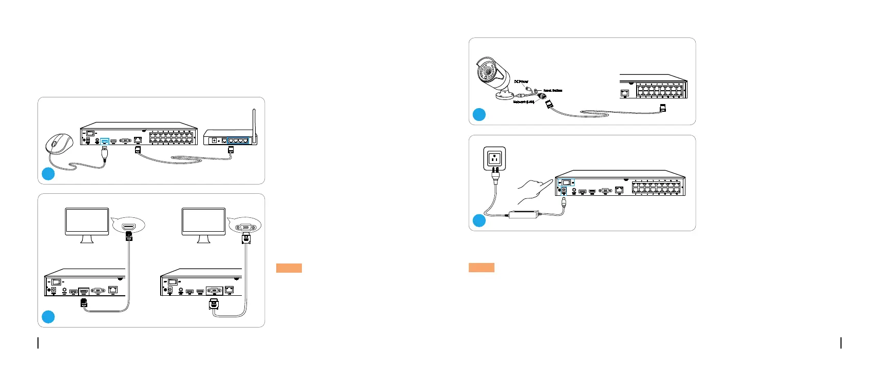
To ensure all components work properly, it is recommended that you connect every part and try
to run the system before a final installation.
Connection Diagram
Connect the NVR (LAN port) to
your router with a network cable.
Next, connect the mouse to the
USB port of the NVR.
Connect the NVR to the monitor
with a VGA or HDMI cable.
Connect cameras to PoE
ports on the NVR.
Connect the NVR to a power
outlet and turn on power switch.
NOTE: There is no VGA
cable included in the package.
NOTE: Some Reolink WiFi cameras also work with Reolink PoE NVR. For more information,
visit https://support.reolink.com and search Make Reolink WiFi Cameras Work
with Reolink PoE-NVRs.
DC48V
IN
AUDIO
OUT
USB HDMI VGA LAN
1
2
3 5 7
4 6 8
9
10
11 13 15
12 14 16
ONOFF
1
DC48V
IN
AUDIO
OUT
USB HDMI VGA LAN
1
2
3 5 7
4 6 8
9
10
11 13 15
12 14 16
ONOFF
4
DC48V
IN
AUDIO
OUT
USB HDMI VGA LAN
eSATA
1
2
3 5 7
4 6 8
9
10
11 13 15
12 14 16
ONOFF
Reset Button
DC Power
Network (LAN)
3
 Loading...