Do you have a question about the RETRO 176 and is the answer not in the manual?
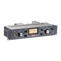
Provides a general description of the 176 Tube Limiting Amplifier, its design, and ease of use.
Details the versatility of the Retro 176 in various audio applications, enhancing dimension and depth.
Lists technical specifications including frequency response, distortion, impedance, and power requirements.
Outlines crucial safety precautions for operating and servicing the 176, including heat and high voltage warnings.
Guidance on rack mounting, ventilation, and avoiding magnetic field interference for optimal performance.
Instructions for setting AC line voltage, fuse replacement, and connecting the power cord.
Details on connecting audio sources via the female XLR connector, including balanced and unbalanced configurations.
Instructions for connecting audio outputs via the male XLR connector, for balanced and unbalanced loads.
Information on strapping multiple 176 limiters for stereo operation using the RCA jack.
Explanation of the grounding scheme via AC mains, chassis, and XLR connectors for safety and noise reduction.
Procedures for initial power-up, checking indicators, and the function of the front door interlock switch.
Describes the hard-wired bypass switch for easy A/B comparisons of the 176's effect.
Explains how the Input Level control adjusts gain reduction with a fixed threshold.
Details the Output Level control for matching levels or providing additional amplifier gain.
Information on adjusting compression ratio in four steps (2:1 to 12:1) and its effect on threshold.
Explains how Attack and Release controls shape dynamic range response and the program-controlled time constant.
Describes the Sidechain HPF's function in controlling low-frequency pumping and its ideal applications.
Explains the Asymmetry Switch for detecting full-wave or half-wave signals for asymmetrical waveforms.
Details the Meter Select switch for monitoring Input, Output levels, and Gain Reduction.
Discusses stereo linking for stable imaging and the benefits of unlinked stereo operation for soundstage.
Overview of the amplifier circuit board and its stages.
Describes the input stage, including the pad, transformer, and impedance matching.
Explains the 6BC8 tube's role in gain reduction controlled by bias voltage.
Details the function of the interstage transformer in separating amplifier stages.
Describes the push-pull amplifier stage using 12AX7 and 12BH7 tubes for gain and balance.
Explains the 6AL5 detector's function in processing signals for ratio and gain reduction controls.
Details how the asymmetry switch affects detector bias and threshold for signal edges.
Explains the Sidechain HPF's implementation and its effect on the detector circuit.
Describes the output level control and T-Pad implementation for attenuating the audio signal.
Overview of the integral balance testing system for calibrating the amplifier.
Explanation of the power supply circuit board and its components.
Traces the AC power path from the IEC receptacle through safety features to the transformer.
Details the power transformer's role in providing various voltages for the unit.
Describes the 5Y3 rectifier tube and its function in the high voltage power supply.
Explains the 0B2 gas discharge tube's function in voltage regulation for the gain reduction stage.
Details the bleeder resistor's function in safely discharging power supply capacitors.
Procedure for zeroing the Gain Reduction meter to compensate for component aging.
Describes the three settings of the Internal Balance Test Switch for calibration.
Step-by-step guide for balancing the 6BC8 stage to prevent compression artifacts.
Procedure for balancing the main amplifier stage after the 6BC8 stage is balanced.
Methods for testing noise and distortion levels, identifying potential faulty components.
Guidelines for performing frequency response tests to ensure flat response within specifications.
Troubleshooting guide for hum and microphonics, often related to tube issues or filament voltage.
Reference to board layouts and schematics for detailed technical understanding.
Information on product warranty, returning units for repair, and obtaining service instructions.
Contact information for technical support, including hours of operation.
Details on the availability and shipping times for replacement parts.
Summary of the product warranty terms, coverage, and limitations.
A form to be completed for obtaining factory service, detailing problem description and contact information.