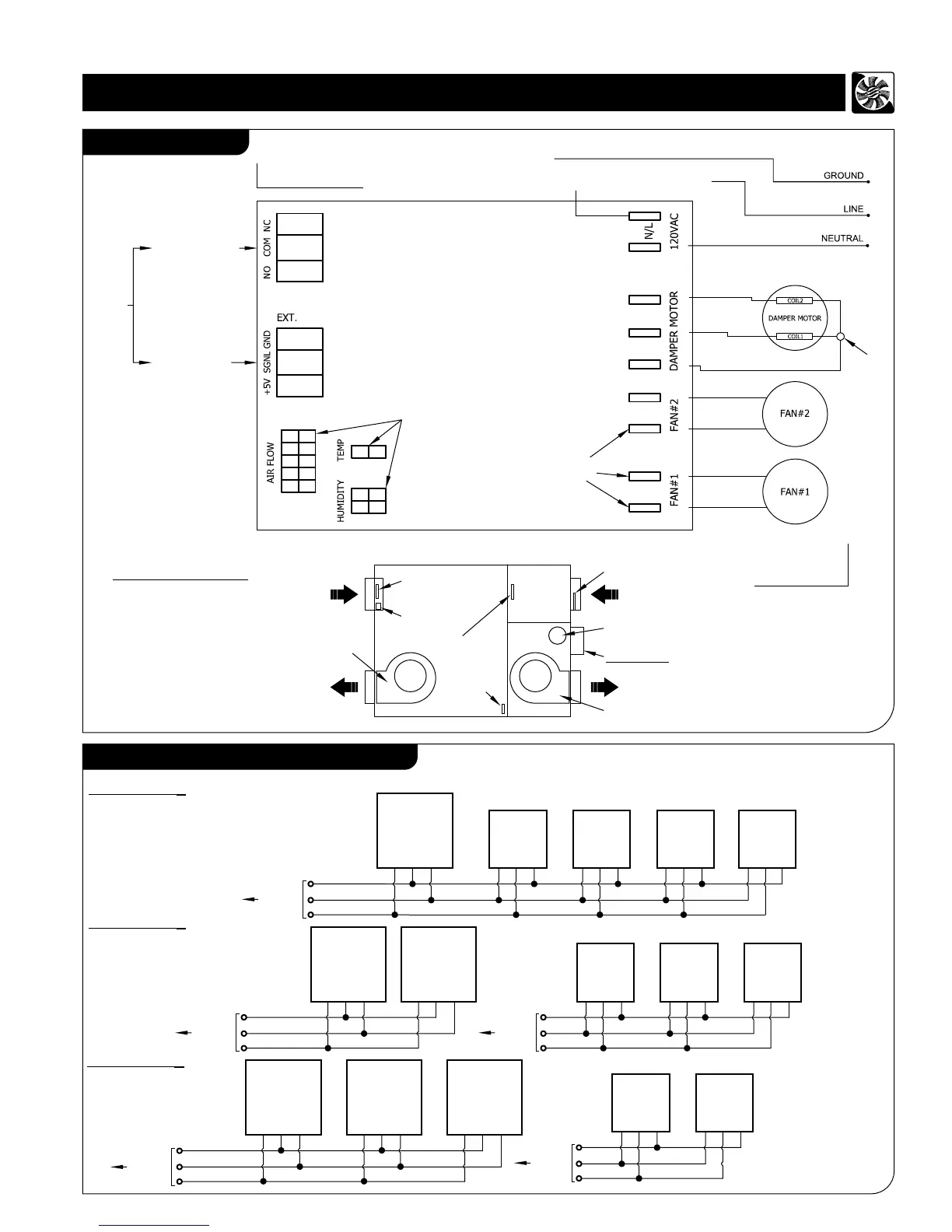
Wiring Diagram
2
Note:
3 Wall-controls and 2 Timer switches or 2 wall controls and 3 Timer switches or
1 wall control and 4 Timer switches can be connected to control board of HRV/ERV
by using three 26 AWG (min.) Copper wires as shown. Maximum wire length is 75ft
in all together.
Option 3:
Option 1:
to Control
Board
Wall Control Units and Timer Switches
High Voltage Harnesses &
HRV/ERV AC Power input
Max current 5A
Control Board Low Voltage
Side Connections
SPLICE
to be
soldered
TERMINAL
TABS
Connection to wall
control units and
timer switches
Headers for HRV/ERV internal
Harness Connections Airflow Sensors,
Humidity Sensor, Defrost Thermistor
Relay Output: SPDT
Max. Recommended
current: 2A
Terminal Blocks for HRV/ERV
External Connections
Low Voltage
INTERLOCKING
RELAY
Connection to the
Furnace, Fan-coil or
Heat Pump
Three wires:
+5V (Power) Signal
and GND
Control Board
HRV/ERV CHASSIS
120 / 1 / 60Hz POWER
HRV/ERV LAYOUT
Humidity
Sensor
Air Flow Sensor
and Diffuser #2
Air Flow Sensor
and Diffuser #1
Temperature
Sensor
Control Board
Fan # 2
(Fresh Air Supply)
Damper Motor
Fan # 1 (Stale Air Exhaust)
Safety
Switch
Option 2:
to Control
Board
(Refer to page 8
to set address
A1, A2, & A3)
Wall
Control
Unit
A1
+5V GND SGNL
+5V
GND
SGNL
Timer
Switch
1
GRN
YEL RED
Timer
Switch
2
GRN
YEL RED
Timer
Switch
3
GRN
YEL RED
to Control
Board
to Control
Board
Timer
Switch
1
GRN
YEL RED
Timer
Switch
2
GRN
YEL RED
Timer
Switch
3
GRN
YEL RED
Wall
Control
Unit
A1
+5V GND SGNL
+5V
GND
SGNL
+5V
GND
SGNL
Wall
Control
Unit
A1
+5V GND SGNL
Wall
Control
Unit
A2
+5V GND SGNL
Wall
Control
Unit
A3
+5V GND SGNL
+5V
GND
SGNL
From Safety Switch
(Mounted on HRV/ERV Housing)
(RED)
(WHITE)
(RED)
Note-:
Air Flow Sensors, Diffusers and Air Flow Harness
are for auto balancing unit only.
Timer
Switch
4
GRN
YEL RED
Wall
Control
Unit
A1
+5V GND SGNL
to Control
Board
Timer
Switch
1
GRN
YEL RED
Timer
Switch
2
GRN
YEL RED
+5V
GND
SGNL