Qoo !. co
u
fl
7.2. AnpassunganNetzschalterbetrieb
De AnpassLrng
für
Netzschalterbetrieb
(siehe
auch
Abschnltt 2.3.)
muss im Geräteinnern
voT
genommen
werden
und darf
desha b nur
vom
Fachmann ausgeführt
werden.
7.2,
Adapting
the amplifier
for manual
on/off
switching
Because
the clrcuit
changes
necessarv
to eJfect
manual
on/off switching
of the e
ectric current
supply
(refer
to section 2.3.)
have to be
per
formed
inside the unit, this
work must
be en
trusted to a ski
led technician.
7.2. Adaptation de
l'interrupteur secteur
Cette adaptation
se falt ä
l'intörleur de I'appareil
(cf.
2.3.)
et
sera de
ce fait confiÖe ä un
profes-
Votsicht:
Vor dem Offnen der
Endstufe
ist Lrnbedingt der
Netzstecker
zu ziehen-
(Auf
den Steckerstiften
im Gerät
iegt
sonst
Netzspannungl)
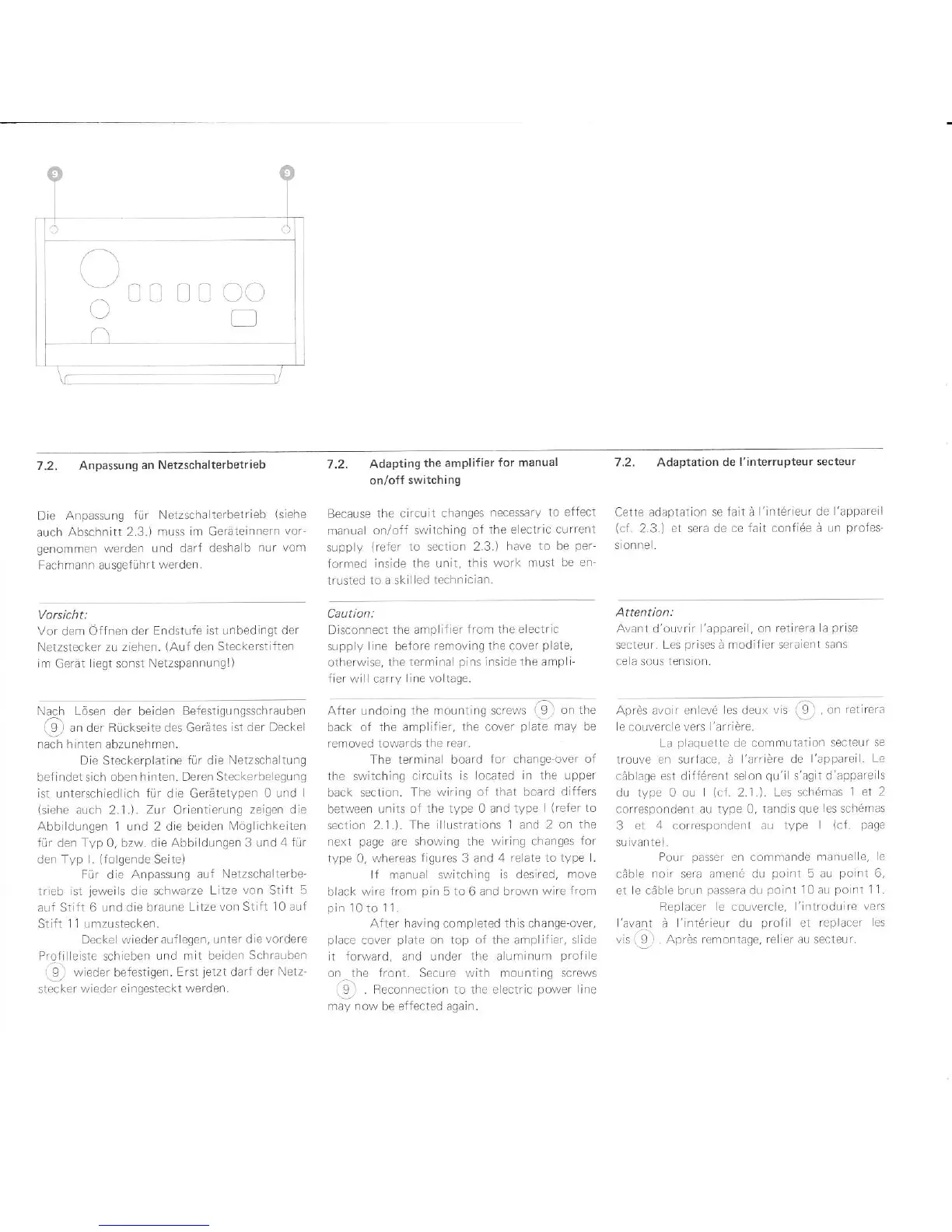
Nalh Lösen der beiden
Befestigungsschralben
(9) an der Rückseite des Gerätes
ist der Deckel
nach hinten
abzunehmen.
Die Steckerplatine
für
die
Netzschaltung
befindet sich oben
hinten. Deren Steckerbelegung
ist unterschiedlich für die Gerätetyp€n
0 und l
(siehe
auch 2.i.).
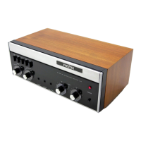
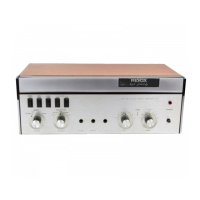
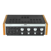
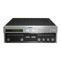
Zur
Orientienrng
zeigen die
Abbildungen 1 und 2 die beiden
IVöglichkeiten
für
den
Typ
0, bzw. die Abbildungen
3 und 4 für
den Typ .
(folgende
Seite)
Für die Anpassung
auf
Netzschalterbe'
trieb lst
jeweils
die schwarze
Litze von Stift 5
auf Stift 6 und
die braune Litze
von Stift 10 auf
Stift 11 umzustecken.
Deckel wiederauf egen, unter
die vordere
Profi le ste schieben
Lrnd mlt beiden Schra!ben
O
wieder befestigen.
Erst
jetzt
darl der Netz-
stecker
wieder elnqesteckt werden.
Caution:
Disconnect
the amplifier trom the
electric
supplv ine before
removing the cover
plate,
otherwise, the
terminal
pins
inside the ampli
fier wil carry
line voltage.
Avanl
d'ouvrir
l'apparei
,
on
retirerä a
prise
secteur. Les
prises
ä modifier seraient sans
ce a sous tension.
After undoing
the mounting screws (Q)
on tne
back
of the ampiifier,
the cover
plate
may be
rernoved towards the
rear,
The
terminal board
for
change-over
of
the switching
circuits is located
in
the
upper
back section.
The wiring of
that board differs
between units of
the type 0 and type
I
(refer
to
section 2.1.). The
illustrations 1 and 2 on the
next
page
are
showing the wiring changes
for
type 0,
whereas
figures
3 and 4
relate to type
lf manual swltching
is
deslred,
move
black wire
{rom
pin
5 to 6
and brown wire
from
pin
10 to
11.
After having completed this change over,
place
cover
plate
on top of the arnplifier,
slide
it forward, and under the aluminum
profi
e
on the front. Secure with mounting screws
Q)
. Reconnection to the electric
power
line
may
now be
effected
again.
Apräs avo r en evd
les
deux
vis
@
,
on
retirera
e
couverc
e vers l'arriöre.
La
plaquette
de cornmutation
secteur se
trouve en surface, ä
I'arriöre de
I'appareil. Le
cäb age est d
ffdrenl
se on
qu'i
s'agit d'appare
s
du type 0 oLr
(c1.
2.1.). Les schdmas
1 et 2
correspondent au type 0, tandis
que
les schdmas
3 et
4
correspondent
au type
I
(cf page
su vante)
Pour
passer
en comrnande manue
e, e
cäble noir sera amen6 du
point
5 au
polnt
6,
et e cäble brLrn
passera
du
point
10 au
point
1]
Rep
acer
e couvercle, I'introdulre
vers
'avant
ä
'intörieur
d!
profil
et replacer
es
vis
(9)
. nprös remontage,
re ier
aLr secteur.
 Loading...