Do you have a question about the Revox A722 and is the answer not in the manual?
Advised to keep original packaging for future transport and protection of the device.
Check warranty card; valid only in country of purchase. Unauthorized repairs void warranty.
Protect from heat/humidity, do not block vents, disconnect power before opening, use AC power only.
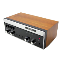
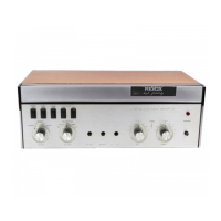
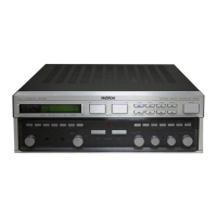
Identifies front panel controls: POWER button, LIMITING buttons, SPEAKER buttons, indicator lights, and headphone jack.
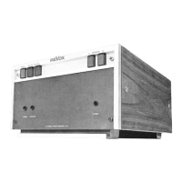
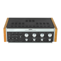
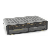
Details rear panel: mounting screws, voltage selector, speaker sockets, 5-pin input, output socket, fuse, and RCA inputs.
Verify voltage selector matches supply and check/replace fuse (15) if necessary.
Main power switch (1) is active unless remote switching via A700/A720 is used.
Type 0 units have disabled power switch; Type I units require switch to be pressed for remote operation.
Remote on/off switching via input (13) when connected to REVOX A700/A720.
Requires internal wiring modification by a technician for manual control, refer to sections 7.2 and 7.3.
Connects to control units (A720/A700) for remote operation. Use NWAN-420 cable.
Alternative inputs for source connection. Requires 0.75V for 60W output.
Connect speakers to sockets A (12) and B (11). Minimum 4 Ohms per speaker.
Use buttons 4 (A) and 5 (B) to switch speaker groups on/off.
Limit output to 20% (12W) or 50% (30W) to protect speakers. OVERLOAD indicator (7) shows limit.
Relay-controlled protection for delayed turn-on, instant turn-off, DC output, and thermal overload.
Connect headphones to jack (8). Buttons 4/5 disengage speakers.
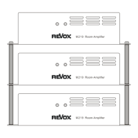
Connect more A722 units via output socket (14) for synchronized remote switching.
Maximum of 4 power amplifiers can be connected to control units (A700/A720).
Details power output, music power, distortion, frequency response, bandwidth, signal-to-noise, and crosstalk.
Covers input impedance, sensitivity, component list, and power supply specifications.
Crucial safety step: disconnect the amplifier from the mains before opening.
Remove cover by undoing screws (9). Terminal board is at the rear.
Reroute wires: black from pin 5 to 6, brown from pin 10 to 11 for manual power switching.
Illustrates remote (Fig 1) and manual (Fig 2) switching configurations for units with serial numbers below 1000.
Illustrates remote (Fig 3) and manual (Fig 4) switching configurations for units with serial numbers 1000 and above.
Specifies DC voltage (approx. 20V) and current (40mA) required for remote switching control.
Details speaker output polarity (DIN reversed) and headphone jack connections (GND, Left, Right).
Max 4 amplifiers per control unit. Diagrams show configurations for 4 amplifiers in groups.
Use Type NWAN 420 interconnecting cables for all cascade connections.