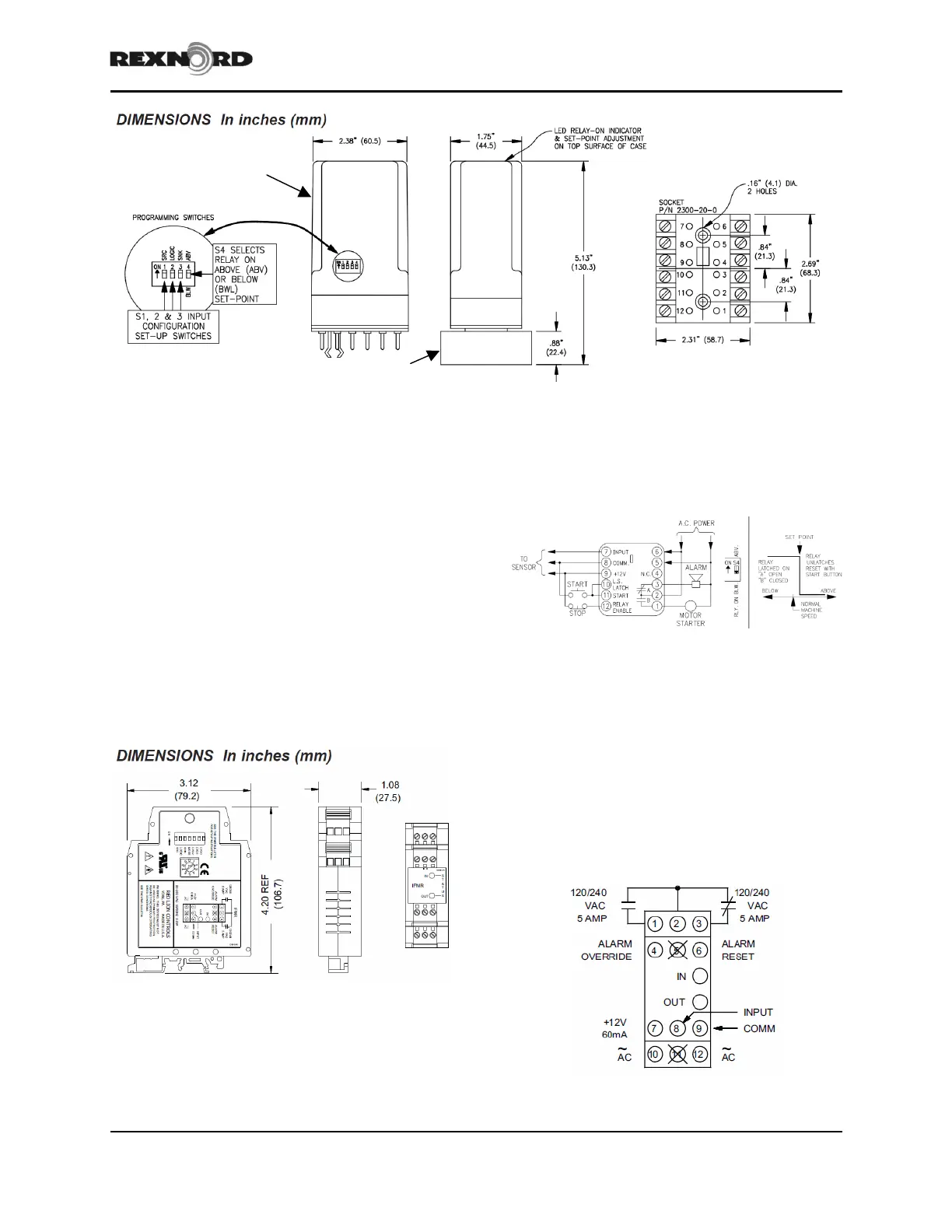
Figure 2 – PRS1 Speed switch mounting dimensions
Rexnord’s over-speed protection system includes the
following components: speed switch (either model
PRS1 or IFMR), magnetic pick-up, and target. The
target is mounted to the clutch hub. A magnetic
pickup is used as the speed sensor and is mounted on
the clutch housing to sense the speed of the target as
it rotates. The speed switch should be mounted in the
motor starter cabinet. Mounting dimensions are
shown in Figure 2 & 3. A 12-pin socket will be
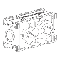
provided with the PRS1 speed switch. The IFMR
switch is equipped with a universal mounting foot for
attachment to standard DIN style mounting rails,
including top hat profile rail according to EN 50 022
– 35x7.5 and 35x15 and G profile rail according to
EN 50 035 – G32.
Figure 3 – IFMR Speed Switch
After all components are installed, the speed switch
can be wired per Figure 4 for PRS1 models or Figure
5 for IFMR models.
!
LATCH,!LOW!SPEED!OPERAT E,!OVER SPEED !DRO POU T!
Pushing the start button energizes and latches the relay and starts the
machine. The relay stays latched as long as machine operates below
set-point speed. If the machine exceeds the set-point speed, the relay
unlatches, sounding the alarm and stopping the machine.
Figure 4 – Wiring diagram – PRS1 speed switch
Model IFMR speed switches should have the primary
power connected to terminals 10 and 12 (labeled
AC). For best results, the AC power should be
relatively “clean” and within 85 to 250 VAC, 48 to
62 HZ and 5.5VA. Drawing power from heavily
loaded circuits or from circuits that also power loads
that cycle on and off, should be avoided. Terminals
1, 2 and 3 are used to connect to the relay output.
Terminal 3 is normally closed contact and terminal 2
is the output relay common.
Figure 5 – Wiring diagram – IFMR speed switch