Do you have a question about the Rexnord Falk A and is the answer not in the manual?
Explains the manufacturer's warranty terms and conditions for the product.
Details the operating limits for horsepower and output speed based on selection.
Information on Falk's repair and rebuild services for equipment.
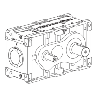
Describes the basic drive identification and its variants like JR, JF, and JSC.
Illustrates shaft mounted, flange mounted, and screw conveyor drive types.
Lists various optional accessories for the drive like motor mounts and backstops.
Instructions for preparing and positioning the drive before installation.
Steps for installing the JR shaft mounted drive, including fasteners.
Recommendations for driven shaft tolerances for TA taper bushing use.
Procedure for installing thin wall bushings onto the driven shaft.
Procedure for installing thick wall bushings onto the driven shaft.
Steps for installing waste packing seals into the seal housing.
Instructions for installing lip seals into the seal housing.
Steps for installing packing gland seals for shaft sealing.
Steps for installing the JSC screw conveyor drive.
Instructions for installing the JF flange mounted drive.
Procedure for installing a backstop on a JR drive.
Torque values for torque arm clevis brackets, spanner nuts, and setscrews.
Detailed steps for installing and tightening the JR drive bushing nut.
Guidance on selecting lubricants and oil capacities for the drives.
Instructions for filling oil in horizontal mounted drives.
Instructions for filling oil in vertical mounted drives.
Steps to check fasteners and other components before initial operation.
Procedure for changing oil after initial operation and flushing.
Regular checks and maintenance tasks like oil level, seals, and fan cleaning.
Guidelines for changing oil, storing, and shutting down drives.
General warnings and procedures for drive repair and accessory servicing.
Steps for removing the JR drive from the driven equipment.
Procedures for removing JF and JSC drives.
Instructions for removing a TA taper bushing from the shaft.
General instructions for disassembling the drive housing.
Steps for removing input and output shaft seals.
Inspection criteria for shaft seal surfaces to ensure proper sealing.
Procedures for correctly installing new shaft seals.
Steps after completing drive repair and before reassembly.
Steps to remove a backstop from the drive.
Guide to using diagrams and part reference numbers for identification.
How to find part descriptions and Falk part numbers.
Recommendation for a set of bearings, seals, and shim-gaskets.
Recommendation for a complete drive in critical applications.
Exploded view diagram illustrating drive components and reference numbers.
List of parts for the drive housing and related components.
Parts list for rotating elements across J05, J09, J14, and J25 types.
Parts for the shaft fan assembly applicable to all ratios.
Cross-reference table for tapered roller bearings from Falk to manufacturers.
Cross-reference table for Viton seals from Falk to manufacturers.
Instructions for cleaning and preparing parts before reassembly.
Steps for assembling tapered roller bearing cups into the housing.
Instructions for assembling the high-speed shaft components.
Steps for assembling the intermediate shaft components.
Instructions for assembling the low-speed shaft components.
Procedures for adjusting bearing preload using shims.
Method for measuring axial float of the low-speed shaft.
Method for measuring axial float of the intermediate shaft.
Method for measuring axial float of the high-speed shaft.
Instructions for installing the backstop component.
Steps for installing the shaft covers.
Final steps for seal installation.
General information, recommendations for lubricants, and viscosity importance.
Details on R&O and EP petroleum-based gear lubricants.
Information on synthetic lubricants for various operating conditions.
Special considerations for synthetic lubricants and food processing.
Guidelines for changing oil based on analysis and usage.
Information on greasing seals for contaminant protection.
Table listing petroleum-based gear lubricants by manufacturer and grade.
Table listing synthetic lubricants by manufacturer, grade, and temperature range.
Scope, limitations, and lubricant needs for backstop installation.
Proper applications, limitations, and indexing warnings for backstop usage.
Steps to prepare the drive before installing a backstop.
Steps for preparing the backstop kit components for installation.
Procedure for installing the backstop into the drive housing.
Instructions for assembling external parts for drives with backstops.
Purpose and availability of the TA removal tool kit.
Steps to prepare the drive and driven shaft before using the tool.
Procedure for using the tool to remove the Quadrive from the shaft.
Torque specifications for H.S. shaft when using the removal tool.
Description, standard, optional assemblies, and guard information for motor mounts.
Steps for assembling the motor mount and base plate.
Instructions for attaching the motor mount to the drive housing.
Steps for positioning and mounting the motor onto the base plate.
Guidance on connecting sprockets, pulleys, or sheaves to the drive.
Purpose of standpipe kits for vertical drive operation.
Instructions for installing standpipes when the high speed shaft is down.
Instructions for installing standpipes when the high speed shaft is up.
General instructions for modifying drives for non-standard mounting.
Overview of standard drive incline limits.
Specific modifications for horizontal drives with inclined shafts.
Table of standard pipe fittings and their Falk part numbers.
Detailed diagrams for inclined shaft modifications.
Part numbers for retaining rings used with bushing nuts.
Part numbers for retaining rings used with thrust plate kits.
Tooth combinations for vibration analysis for Types J05, J09, J14, and J25 drives.
Lip seal part numbers for Type JSC seal housing.
Table detailing dimensions for tapered drive shafts.
Purpose of the appendix for using TA taper bushings with straight shafts.
Requirements for drive shafts and retaining rings.
Steps for installing the drive shaft with TA taper bushing.
Fastener data for thrust plates used with TA taper bushings.
Bolt size and torque data for removal procedures.
Dimensions for bushings used with the largest bore sizes.
Purpose of the appendix for TCB kit usage with straight shafts.
Requirements for drive shafts when using the TCB kit.
Steps for installing the drive shaft with the TCB kit.
Bolt size and torque data for removal procedures.
Dimensions for bushings included in the TCB kit.
Instructions to assemble motor and mount as per Appendix D.
Steps for attaching belt guard brackets to the motor mount.
Procedure for assembling the backplate to the guard brackets.
Instructions to assemble motor and mount as per Appendix D.
Steps for attaching guard bracket and adapter.
Procedure for assembling backplate to bracket and fan.
Overview of electric fan installation procedures.
Steps for installing the electric fan and shroud.