INTRODUCTION — These instructions are for use when a screw
conveyor 5107 - 5315JSC drive is to be used and the following
conditions exist: Falk standard or 316 stainless steel JSC tapered
drive shafts can not be used due to special extension dimensions or
materials; or manufacturing a special tapered drive shaft is not
feasible. Use this appendix to retrofit existing applications or for
outfitting new installations where the above conditions warrant. For
tapered shaft recommendations, see Appendix H.
This appendix will allow the use of a straight (non tapered) drive
shaft with a special bushing conversion kit on screw conveyor
applications. This kit provides one bushing bore per drive size as
shown in Table 4. Provided in this appendix are dimensions for
drive shaft recommendations and instructions for the installation
and removal of the assembly.
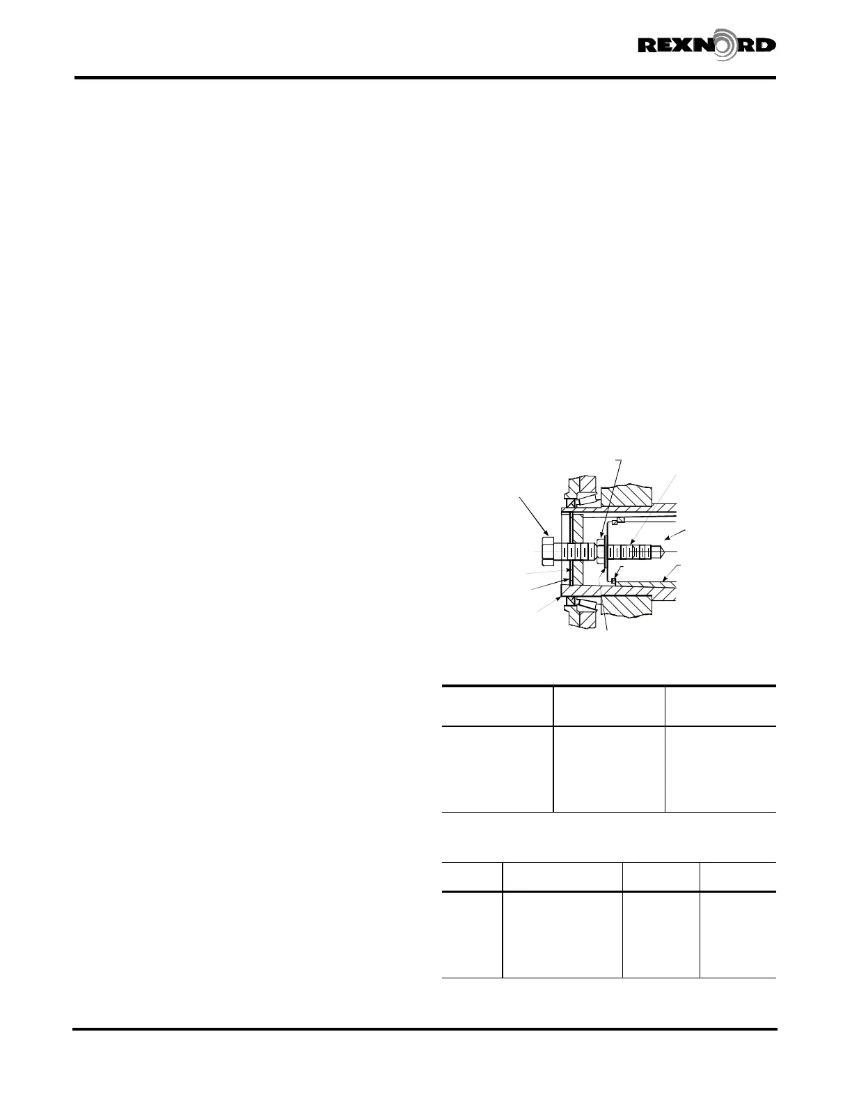
FIGURE 2 — The hollow shaft of the drive has a tapered bore
which accepts the tapered bushing. When the bushing is drawn
into the taper a clamping force is applied to the drive shaft. The
drive shaft is drawn into the hollow shaft via a fastener in the thrust
plate. The bushing seats against a shoulder on the drive shaft and
is drawn into the drive with the shaft. Removal is accomplished by
using a jackscrew in the thrust plate and forcing the drive shaft out
of the drive. The retaining ring in the drive shaft assures that the
bushing will be removed along with the shaft.
The packing gland sealing option (Sizes 5107-5315) is usable
with the bushing kit, but the clamp ring must be assembled from
the extension end of the drive shaft on Sizes 5307 and 5315.
DRIVE SHAFT RECOMMENDATIONS — The recommendations
for the drive shaft consist of two major features. The first is the
shoulder which must be provided in the location shown in Figure 2.
This shoulder provides the backing necessary to draw the bushing
into the taper. A permanently fixed shoulder must be provided in
order for this design to be effective. The shoulder may be a welded
collar or an integral step. SET COLLARS ARE NOT ACCEPTABLE. A
retaining ring may be used in the drive shaft, to provide the shoulder,
but stress concentrations can occur at the groove and therefore shaft
stresses must be checked. The second major feature on the shaft is
the retaining ring groove in the shaft end. This feature is
recommended to ensure positive removal of the bushing when the
drive shaft is removed from the drive. The threaded hole in the end
of the drive shaft accepts the thrust plate fastener.
WARNING: Lock out power source and remove all external
loads from system before servicing drive or accessories.
INSTALLATION PROCEDURE — With the shaft manufactured
per the recommendations shown, proceed as follows:
5107-5215JSC — The seal housing may be assembled to the
drive before or after the drive shaft is installed into the drive,
depending on the shaft extension diameter.
5307-5315JSC — The seal housing must be assembled over
the drive shaft from the extension end of the shaft, or the shaft
shoulder must be fixed in position after the seal housing is
assembled over the drive shaft (see Figure 2).
ALL JSC DRIVES — Slide the bushing (large end first) onto the
drive shaft until it contacts the shoulder on the shaft. Insert the
key through the bushing and into the drive shaft keyway. Install
the retaining ring into the groove in the drive shaft. Line up the
keyway in the drive hollow shaft with the key in the drive shaft
and slide shaft/bushing assembly into the hollow shaft. Attach
the seal housing to the drive with the fasteners provided.
Tighten fasteners to torque given in Table 1. Assemble the thrust
plate and retaining ring into the counterbore in the hollow shaft.
Insert the thrust plate fastener through the thrust plate and
thread into the drive shaft end. Tighten to the torque given in
Table 2. Install all covers and guards.
REMOVAL PROCEDURE — Remove low speed shaft input end
cover. Remove the thrust plate fastener, retaining ring and thrust
plate from the hollow shaft. Refer to Table 3 and select a
backing bolt and flat washer and install them into the drive shaft
as illustrated in Figure 1. The head of the backing bolt provides
a working surface for the removal bolt. Reinsert the thrust plate
and retaining ring into the hollow shaft and select a removal
bolt from Table 3. Thread the removal bolt into the thrust plate
until it contacts the backing bolt head. Tighten the removal bolt
to the torque indicated in Table 3. (If the thrust plate rotates in
the shaft, align the slot in the plate with the hollow shaft keyway
and insert a screwdriver or piece of key stock to prevent rotation
of the plate.) After torquing the bolt, as instructed, strike the bolt
sharply with a hammer and retorque the bolt if separation of the
drive from the shaft did not occur. Repeat this procedure,
retorquing the bolt after each blow, until separation occurs.
Rexnord Industries, LLC 3001 W. Canal St., Milwaukee, WI 53208-4200 USA378-200 (PN-2128394)
Telephone: 414-342-3131 Fax: 414-937-4359November 2010
e-mail: info@rexnord.com web: www.rexnord.comSupersedes 6-07
REMOVAL
BOLT
IN DRIVE SHAFT
DRIVE SHAFT
BUSHING
RETAINING
RING
RETAINING
RING
HOLLOW
SHAFT
THRUST
PLATE
Figure 1
TABLE 1 — Seal Housing Fastener Tightening
Torque (Non-Lubricated Fasteners)
DRIVE
SIZE
Fastener Size
Max Tightening
Torque
lb-ft (Nm)
5107 .500-13UNC 69 (94)
5115 .625-11UNC 137 (186)
5203 .750-10UNC 245 (332)
5207 .875- 9UNC 380 (515)
5215 1.000- 8UNC 567 (769)
5307 1.000- 8UNC 792 (1074)
5315 1.000- 8UNC 792 (1074)
TABLE 2 — Thrust Plate Fastener Data
s
(Non-Lubricated Fasteners)
DRIVE SIZE Fastener Size & Grade
Max. Tightening
Torque lb-ft (Nm)
Min Thread Depth
Inches (mm)
5107 .500-13UNC x 3.50, GR.8 92 (125) 2.00 (50,8)
5115 .500-13UNC x 4.00, GR.8 92 (125) 2.00 (50,8)
5203 .625-11UNC x 3.50, GR.8 183 (248) 2.00 (50,8)
5207 .625-11UNC x 3.50, GR.8 183 (248) 2.00 (50,8)
5215 .875- 9UNC x 5.00, GR.8 533 (723) 2.50 (63,5)
5307 1.000- 8UNC x 5.00, GR.5 567 (769) 2.50 (63,5)
5315 1.000- 8UNC x 5.00, GR.8 792 (1074) 2.50 (63,5)
s
Fasteners may be hex socket head or hex head except for Size 5307, which
must be a hex head to clear input end cover.
Drive Shaft Recommendations Using (TCB) Kit
Shaft Mounted Drives Model A
(Page 40 of 44) Sizes 5107-5315
 Loading...