Motor Mount Installation
Introduction
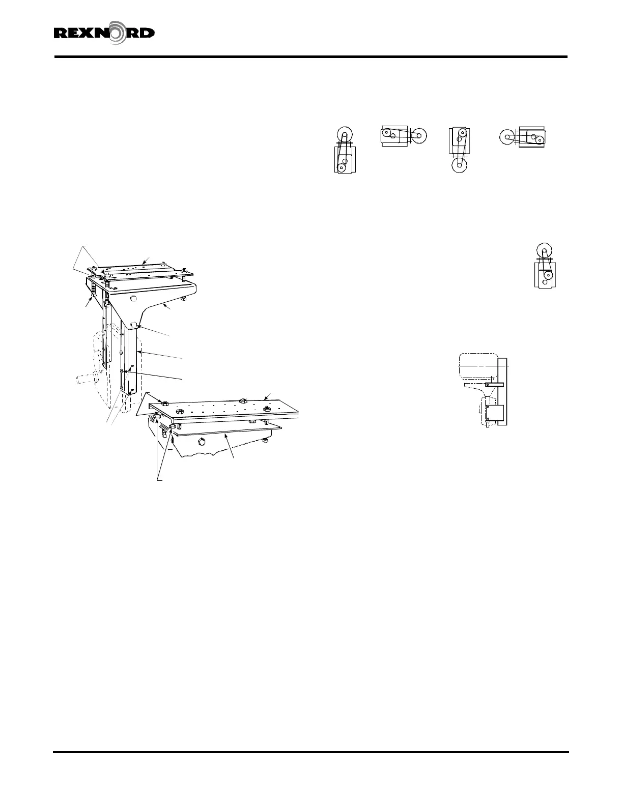
The Falk Equi-Poised motor mount is an all steel weldment that
bolts directly to the drive housing of Falk Shaft Mounted (Type
JR), Flange Mounted (Type JF) and Screw Conveyor (Type JSC)
Drives, as shown in Figure 1.
This modern design provides a simple means of tensioning
V-belts or chains with adjusting screws. Motor baseplates are
available from Factory predrilled for NEMA and IEC standard
foot-mounted motors within the rated capacity of the drive.
Assembly Instructions
From Figure 2, determine which assembly is required. For
minimum bearing loads on driven machine, minimum shaft
deflection and the most economical belt selections, use the 6
o’clock mounting position, high speed shaft relative to the low
speed shaft, illustrated in Figure 1. The motor/drive assembly
can also be mounted in positions shown in Figure 2. Always
locate air vent at the top of horizontal drives.
Letter = Motor Mount Position
Clock = Drive High Speed Shaft Position
OPTIONAL ASSEMBLY
The motor mount may be mounted on the high
speed shaft end of FLANGE MOUNTED DRIVES – JF
(also SCREW CONVEYOR DRIVES – JSC) if
clearance over the trough end permits) when
increased motor mount clearance is required at the
driven machine. Consult Factory for SHAFT
MOUNTED DRIVES – JR.
Guards
CAUTION: Consult applicable local
and national safety codes for proper
guarding of rotating members.
Mounting holes located on the
motor mount supports are
provided for installing a belt
guard. Refer to Appendix L for
installation of Falk V-Belt guards.
WARNING: Remove all external
loads from system before servicing drive or accessories.
1. ASSEMBLE MOTOR MOUNT — Loosely assemble support
legs to the base plate support as shown in Figure 1.
NOTE: Nuts on inside for Sizes 5107 thru 5115.
Nuts on outside for Sizes 5203 thru 5315.
For NEMA motor frames 254 and larger or IEC motor frames
160 & larger, fasten adapter plate to base plate support and
tighten adapter fasteners to the torque specified in Table 1.
Assemble adjusting screws to base plate support (or adapter
plate when used). Assemble motor base plate to adjusting
screws with a jam nut above and below the motor base plate.
Motor base plates on Size 5207 and larger drives with 254
frame and larger motors have turned down edges. These base
plates may be inverted to improve access to the lower jam
nuts provided the turned up edges do not interfere with the
motor conduit box or electrical wiring.
Rexnord Industries, LLC (PN-2128394) 378-200
3001 W. Canal St.,Milwaukee, WI 53208-4200 USA Telephone: 414-342-3131 November 2010
Fax: 414-937-4359 e-mail: info@rexnord.com web: www.rexnord.com Supersedes 6-07
BASE PLATE SUPPORT
ADJUSTING
SCREW
JAM NUT
MOTOR
BASE PLATE
BASE PLATE SUPPORT
FASTENERS
SUPPORT LEG (ATTACHED
TO INPUT SIDE OF DRIVE)
SUPPORT LEG
FASTENERS
BELT GUARD
MOUNTING HOLES
ADAPTER PLATE
ADAPTER FASTENERS
MOTOR
BASE PLATE
JAM NUT
A6
(6 o'clock)
B9
(9 o'clock)
C12
(12 o'clock)
D3
(3 o'clock)
STANDARD ASSEMBLIES
Figure 2
OSHA type
guard when
specified.
Dimensions
to suit
components.
Figure 1
Shaft Mounted Drives Model A
Sizes 5107-5315 (Page 31 of 44)


 To Next Page