Vertical Standpipe Installation
Introduction
The following instructions apply to the installation of standpipe kits
to standard drives mounted for vertical operation (high speed shaft
up or down). Drawings are representative of this series of drives
and may not agree in exact detail with all drive sizes.
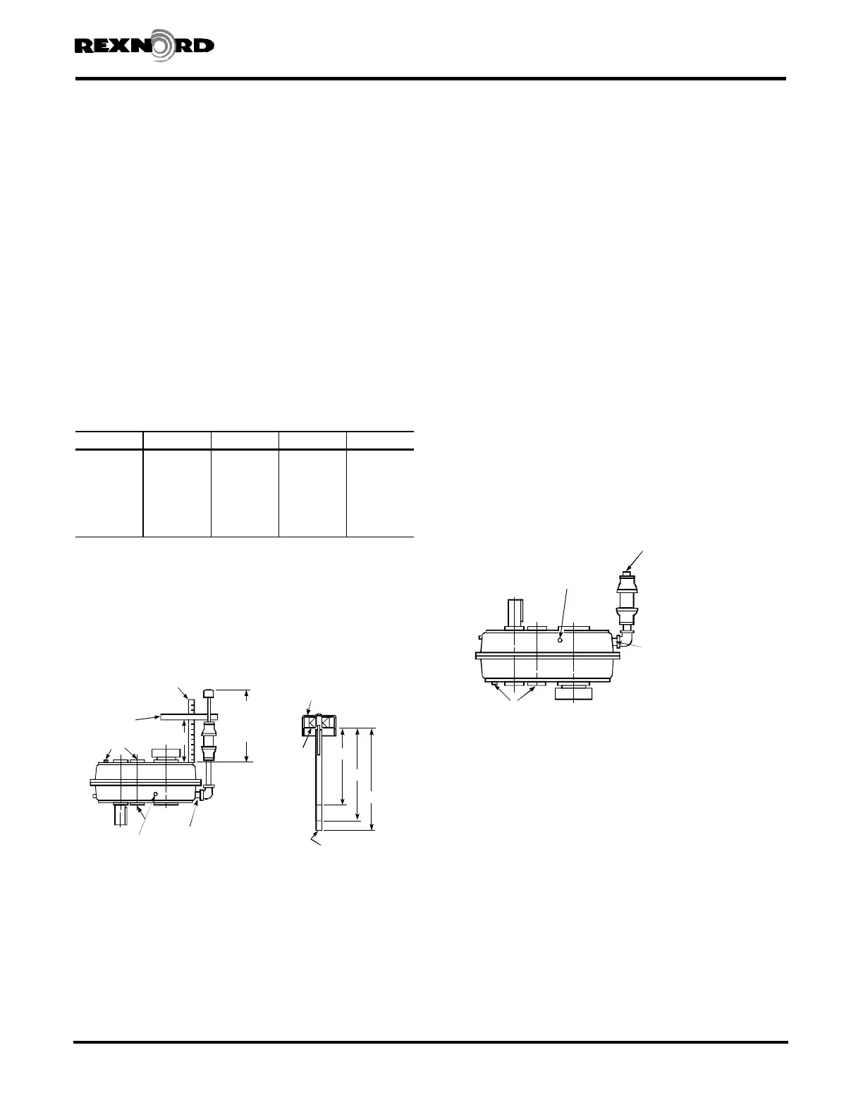
High Speed Shaft Down — Figure 1.
1. After installing the drive per the Owners Manual installation
instructions, determine which of the lower side plug locations
on the drive will provide the best location for the standpipe,
observing clearance required to remove dipstick (Dimension
D, Table 1). Discard the air vent. When the air vent location is
not used for the standpipe, relocate the pipe plug from the
selected standpipe location to the air vent location. Recoat
pipe plug threads with Permatex #3 or equivalent sealant
before reinstalling.
2. Coat all pipe threads of kitted parts with Permatex #3 or
equivalent sealant.
3. Assemble kitted parts to the drive as illustrated in Figure 1
and then secure the standpipe with an external support to
maintain its vertical position.
4. Carefully measure Dimension “X” as illustrated in Figure 1.
5. From Table 1:
X + A equals oil level “Full” mark.
X + B equals oil level “Low” mark.
X + C equals dipstick length.
6. Scribe Dimensions X + A and X + B on the dipstick as
illustrated in Figure 1. Make measurements from the felt
pad in the dipstick cap.
7. Lightly chisel permanent oil level marks on the scribed lines
and cut the dipstick to the length marked. File end of
dipstick smooth.
8. Install magnetic drain plug furnished in oil drain location.
9. Remove the oil filler plug. Add oil until the oil level reaches
the “Full” mark on the dipstick. Coat the filler plug (not
vented) with Permatex #3 or equivalent sealant and
replace it.
10. Filler plug must always be removed to relieve entrapped
air before checking oil level.
High Speed Shaft Up — Figure 2.
1. After installing the drive per the Owners Manual installation
instructions, determine which of the upper four side plug
locations on the drive will provide the best location for the
standpipe, observing clearance required to remove dipstick
(Dimension D, Table 1). Discard the air vent. When the air
vent location is not used for the standpipe, relocate the pipe
plug from the selected standpipe location to the air vent
location. Recoat pipe plug threads with Permatex #3 or
equivalent sealant before reinstalling.
2. Coat all pipe threads of kitted parts with Permatex #3 or
equivalent sealant.
3. Assemble kitted parts to drive as illustrated in Figure 2 and
then secure the standpipe with an external support to
maintain its vertical position.
4. See Figure 1 and follow steps 4 thru 7 at left.
5. Install magnetic drain plug furnished in oil drain location.
6. Remove one of the three oil level plugs. Add oil through the
standpipe until the oil level reaches the plug hole. Coat the
plug with Permatex #3 or equivalent sealant and replace it.
Be sure to use only the vented filler plug in the standpipe.
Rexnord Industries, LLC (PN-2128394) 378-200
3001 W. Canal St.,Milwaukee, WI 53208-4200 USA Telephone: 414-342-3131 November 2010
Fax: 414-937-4359 e-mail: info@rexnord.com web: www.rexnord.com Supersedes 6-07
TABLE 1 — Dimensions - Inches (mm)
DRIVE SIZE A B C D
5107 0.90 (23) 1.10 (28) 1.60 (41) 19.2 (488)
5115 0.90 (23) 1.10 (28) 1.60 (41) 18.3 (465)
5203 1.08 (27) 1.28 (33) 1.78 (45) 18.2 (462)
5207 1.14 (29) 1.34 (34) 1.84 (47) 20.4 (518)
5215 1.54 (39) 1.74 (44) 2.24 (57) 22.1 (561)
5307 1.54 (39) 1.84 (47) 2.34 (59) 23.7 (602)
5315 1.70 (43) 2.20 (56) 2.70 (69) 23.1 (587)
DIPSTICK
CAP
FELT
PAD
FILE SMOOTH
OIL
LEVEL
MARKS
FULL
LOW
OIL DRAIN
USE REDUCING
BUSHING FOR
SIZES 5107 THRU 5207
FILLER
PLUG
STRAIGHT
EDGE
SCALE
X
D
CLEARANCE
FOR DIPSTICK
REMOVAL
X + A
X + B
X + C
{
Figure 1
OIL LEVEL
OIL DRAIN
USE REDUCING BUSHING
FOR SIZES 5107 THRU 5207
VENTED FILLER PLUG
Figure 2
Shaft Mounted Drives Model A
Sizes 5107-5315 (Page 33 of 44)
 Loading...