INTRODUCTION — These instructions are for use when a flange
mounted 5107-5315JF drive is to be used and the manufacture of
a tapered drive shaft is not feasible. For JF tapered drive shaft
recommendations, see Appendix H. Use this appendix to retrofit
existing applications or for outfitting new installations. Parts
required are the Basic drive, TA Taper bushing and a thrust plate
kit.
This appendix will allow the use of a straight drive shaft with the
tapered bushing (without spanner nut) on flange mounted
applications. Provided are dimensions (Table 4) for shaft
recommendations and instructions for the installation and
removal of the assembly. All bushing bore sizes, which are
available in the standard Quadrive, are possible with this setup.
Drives are provided with tapped holes in the output face of the
housing along with a female register to allow mounting to the
driven equipment. JF drives are mounted to the equipment
without the use of an adapter flange. Optional adapter flanges
are available, consult the Factory.
FIGURE 2 — The hollow shaft of the drive has a tapered bore
which accepts the tapered bushing. When the bushing is drawn
into the taper a clamping force is applied to the drive shaft. The
drive shaft is drawn into the hollow shaft via a fastener in the
thrust plate. The bushing seats against a shoulder on the driven
shaft and is drawn into the drive with the shaft. Removal is
accomplished by using a jackscrew in the thrust plate and
forcing the drive shaft out of the drive. The retaining ring in the
drive shaft assures that the bushing will be removed along with
the shaft.
DRIVE SHAFT RECOMMENDATIONS — The
recommendations for the drive shaft consist of two major
features. The first is the shoulder which must be provided in the
location shown in Figure 2. This shoulder provides the backing
necessary to draw the bushing into the taper. A permanently fixed
shoulder must be provided in order for this design to be effective.
The shoulder may be a welded collar or an integral step. SET
COLLARS ARE NOT ACCEPTABLE. A retaining ring may be used,
in the driven shaft, to provide the shoulder, but stress
concentrations occur at the groove and therefore shaft stresses
must be checked. The second major feature on the shaft is the
retaining ring groove in the shaft end. This feature is
recommended to ensure positive removal of the bushing when
the drive shaft is removed from the drive. The threaded hole in
the end of the drive shaft accepts the thrust plate fastener.
WARNING: Lock out power source and remove all external
loads from system before servicing drive or accessories.
INSTALLATION PROCEDURE — With the drive shaft
manufactured per the recommendations shown, and the
bushing selected for the proper shaft diameter, remove and
discard the retaining ring and spanner nut from the
bushing assembly.
Slide the bushing (flange end first) onto the drive shaft until it
contacts the shoulder on the shaft. Insert the key through the
bushing and into the drive shaft keyway. Install the retaining ring
into the groove in the drive shaft. Bring the drive into position,
line up the hollow shaft keyway with the key and slide the
bushing and drive shaft into the hollow shaft bore.
Attach the drive to the mounting surface with fasteners (not
provided). Refer to Table 1 for fastener size and tightening
torque. Assemble the thrust plate and retaining ring into the
counterbore in the hollow shaft. Insert the thrust plate fastener
through the thrust plate and thread into the drive shaft end.
Tighten to the torque given in Table 2. Install all covers
and guards.
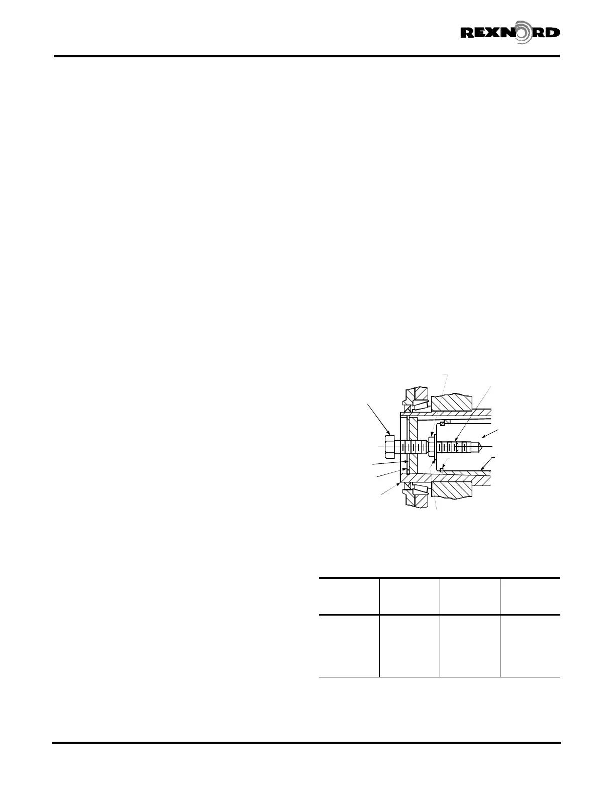
REMOVAL PROCEDURE — Remove low speed shaft input
end cover. Remove the thrust plate fastener, retaining ring
and thrust plate from the hollow shaft. Refer to Table 3 and
select a backing bolt and flat washer and install them into
the drive shaft as illustrated in Figure 1. The head of the
backing bolt provides a working surface for the removal bolt.
Reinsert the thrust plate and retaining ring into the hollow
shaft and select a removal bolt from Table 3. Thread the
removal bolt into the thrust plate until it contacts the backing
bolt head. Tighten the removal bolt to the torque indicated in
Table 3. (If the thrust plate rotates in the shaft, align the slot in
the plate with the hollow shaft keyway and insert a screw driver
or piece of key stock to prevent rotation of the plate.) After
torquing the bolt, as instructed, strike the bolt sharply with a
hammer and retorque the bolt if separation of the drive from
the shaft did not occur. Repeat this procedure, retorquing the
bolt after each blow, until separation occurs.
Rexnord Industries, LLC 3001 W. Canal St., Milwaukee, WI 53208-4200 USA378-200 (PN-2128394)
Telephone: 414-342-3131 Fax: 414-937-4359November 2010
e-mail: info@rexnord.com web: www.rexnord.comSupersedes 6-07
REMOVAL
BOLT
BACKING BOLT
TAPPED HOLE
IN DRIVE SHAFT
DRIVE SHAFT
BUSHING
RETAINING
RING
FLAT WASHER
RETAINING
RING
HOLLOW
SHAFT
THRUST
PLATE
Figure 1
Drive Shaft Recommendations Using TA Taper Bushing
TABLE 1 — JF Drive – Foundation Fastener &
Tightening Torque
(Non-Lubricated Fasteners)
DRIVE
SIZE
Fastener Size
& Grade
Max. Tightening
Torque
lb-ft (Nm)
Min. Fastener
Engagement Into
Drive Housing
Inch (mm)
5107 .500-13UNC, GR. 5 69 (94) .76 (19,3)
5115 .625-11UNC, GR. 5 137 (186) .94 (23,9)
5203 .750-10UNC, GR. 5 245 (332) .76 (19,3)
5207 .875- 9UNC, GR. 5 380 (515) .88 (22,4)
5215 1.000- 8UNC, GR. 5 567 (769) 1.00 (25,4)
5307 1.000- 8UNC, GR. 8 792 (1074) 1.24 (31,5)
5315 1.000- 8UNC, GR. 8 792 (1074) 1.24 (31,5)
Shaft Mounted Drives Model A
(Page 38 of 44) Sizes 5107-5315
 Loading...