Rexnord Industries, LLC (PN-2128394) 378-200
3001 W. Canal St.,Milwaukee, WI 53208-4200 USA Telephone: 414-342-3131 November 2010
Fax: 414-937-4359 e-mail: info@rexnord.com web: www.rexnord.com Supersedes 6-07
TABLE 4 — Dimensions – Inches (mm)
Taper
Conversion
Bushing
Kit
†
(TCB)
Kit
Part
No.
A
± 0.010
(± 0.25)
B
± 0.030
(± 0.75)
C
‡
DA
l
DB
n
+0.000, - 0.003
(+0.00, - 0.08)
Retaining Ring
t
Keyway
Q
S
T
Min
Weld/Integral
Flange
Groove
Mfg.
No.
Max
O.D.
W H
L
Min
F G U V
TCB5107J-
1.438
0766041
4.780
(121,41)
5.000
(127,00)
2.625 (66,68)
2.414 (61,32)
1.4375
1.750
(44,45)
1.295
1.287
0.056
0.060
Spir O Lox
RSN-137
1.500 0.375 0.1875
3.563
(90,50)
0.500-13
2.00
(50,8)
. . . . . .
TCB5115J-
1.938
0766042
5.330
(135,38)
5.500
(139,70)
2.452 (62,28)
2.226 (56,54)
1.9375
2.375
(60,33)
1.735
1.725
0.068
0.072
Spir O Lox
RST-181
2.000 0.500 0.2500
4.000
(101,60)
0.500-13
2.00
(50,8)
. . . . . .
TCB5203J-
2.188
0766043
5.310
(134,87)
5.625
(142,88)
2.346 (59,59)
2.099 (53,31)
2.1875
2.625
(66,68)
1.952
1.940
0.086
0.091
Spir O Lox
RSN-206
2.250 0.500 0.2500
4.625
(117,48)
0.625-11
2.00
(50,8)
. . . . . .
TCB5207J-
2.438
0766044
5.890
(149,61)
6.250
(158,75)
2.548 (64,72)
2.260 (57,40)
2.4375
3.000
(76,20)
2.290
2.278
0.056
0.060
Spir O Lox
RS-236
2.500 0.625 0.3125
5.625
(142,88)
0.625-11
2.00
(50,8)
. . . . . .
TCB5215J-
2.938
0766045
6.860
(174,24)
7.125
(180,98)
2.475 (62,87)
2.188 (55,58)
2.9375
3.500
(88,90)
2.728
2.716
0.056
0.060
Spir O Lox
RS-281
3.062 0.750 0.3750
5.875
(149,22)
0.875-9
2.50
(63,5)
. . . . . .
TCB5307J-
3.438
0766046
6.530
(165,86)
6.860
(174,24)
3.527 (89,59)
3.235 (82,17)
3.4375
3.500
(88,90)
3.172
3.160
0.103
0.108
Spir O Lox
RSN-334
3.625 0.875 0.4375
6.750
(171,45)
1.000-8
2.50
(63,5)
0.375
s
(9,52)
4.250
(107,95)
TCB5315J-
3.438
0785785
7.030
(178,56)
8.500
(215,90)
3.560 (90,42)
3.266 (82,96)
3.4375
3.500
(88,90)
3.263
3.251
0.103
0.108
Spir O Lox
RSN-343
. . . 0.875 0.4375
8.250
(209,55)
1.000-8
2.50
(63,5)
0.375
s
(9,52)
4.250
(107,95)
†
Kit consists of: Bushing, thrust plate, fastener, key, retaining ring, and hardware.
‡
The range of C dimension is the variation which may occur due to axial compression and manufacturing tolerances.
l Shaft diameter tolerances are per AGMA as follows: to 1.50" = +.000", -.004"; over 1.50" to & including 2.50" = +.000", -.005"; over 2.50" to & including 4.00" =
+.000", - .006".
n
If a lip type seal is used, a 32rms finish is recommended.
t
Smalley retaining rings may be used instead of Spir O Lox by substituting WS for RS, WST for RST or WSM for RSN.
Q
Inch keyway width tolerances are as follows: over .312" to & including .500" = +.0025", -.0000"; over .500" to & including 1.000" = +.0030", -.0000"; 1.000". Inch
keyway depth tolerance is +.010”, -.000”.
s Maximum for use with packing gland seal.
TABLE 3 — Removal & Backing Bolt Size and
Tightening Torque
DRIVE
SIZE
Removal Bolt Size &
Min Length – Inches
Max Tightening
Torque lb-ft (Nm)
Backing Bolt Size &
Max Length – Inches
5107 .625-11UNC x 1.75 133 (180) .500-13UNC x 1.25
5115 .625-11UNC x 1.75 133 (180) .500-13UNC x 1.25
5203 .750-10UNC x 2.00 242 (328) .625-11UNC x 1.75
5207 .750-10UNC x 2.00 242 (328) .625-11UNC x 1.75
5215 1.000- 8UNC x 2.50 567 (769) .875- 9UNC x 2.25
5307 1.125- 7UNC x 3.00 742 (1006) 1.000- 8UNC x 2.50
5315 1.125- 7UNC x 3.00 742 (1006) 1.000- 8UNC x 2.50
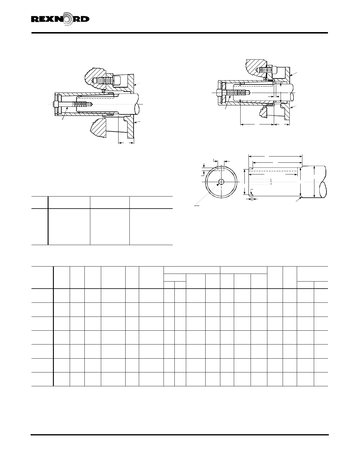
Drive Shaft Recommendations Using (TCB) Kit
MOUNTING
SURFACE
MOUNTING
SURFACE
C
THRUST
PLATE
FASTENER
Figure 2
5107 - 5215JSC
MOUNTING
SURFACE
MOUNTING
SURFACE
V
U
THRUST
PLATE
FASTENER
A C
5307 & 5315JSC
B
A
W (Keyway)
H (Keyway)
L (Keyway)
0.010" (0,25 mm) R MAX.
IN GROOVE CORNERS
F
1-S DIA. UNC TAPPED HOLE
T-DEEP
DB
G
.06" (1,5 mm) RADIUS
DA
Shaft Mounted Drives Model A
Sizes 5107-5315 (Page 41 of 44)
 Loading...