Modifications for Non-Standard Mounting Positions
Rexnord Industries, LLC (PN-2128394) 378-200
3001 W. Canal St.,Milwaukee, WI 53208-4200 USA Telephone: 414-342-3131 November 2010
Fax: 414-937-4359 e-mail: info@rexnord.com web: www.rexnord.com Supersedes 6-07
L
L
L
L
L
*
*
L
*
L
*
H.S. Shaft Inclined 20 to 30° Up
H.S. Shaft Inclined 5 to 30° Down
3 O’Clock H.S.S. Up
3 O’Clock H.S.S. Down
5107 THRU 5315 = STD
5107 THRU 5315 = STD
5107 THRU 5307 = STD
5315 = KIT 0786776
5107 THRU 5315 = STD
5107 = 5-25° .375 E/P
5107 = 26-30° .375 E/C, .375 X 1.00N & KIT 0786775
5115 = 5-20° .375 E/C & .375 X 1.00N
5115 = 21-30° .375 E/C, .375 X 2.00N & KIT 0786775
5203 = 5-30° .375 E/C & .375 X 1.50N
5207 = 5-15° .375 E/P
5207 = 16-30° .375 E/C & .375 X 2.00N
5215 = 5-30° .500 E/C & .500 X 2.50N
5307 = 5-30° .500 E/C & .500 X 2.50N
5315 = 5-30° .500 E/C & .500 X 2.50N
5107 = .375 E/P
5115 = .375 E/C & .375 X 2.00N
5203 = .375 E/C & .375 X 1.50N
5207 = .375 E/C & .375 X 2.00N
5215 = .500 E/C & .500 X 2.50N
5307 = .500 E/C & .500 X 2.50N
5315 = .500 E/C & .500 X 2.50N
5107 = 5-15° STD
5107 = 16-30° .375 E/P & KIT 0786775
5115 = 5-15° .375 E/P
5115 = 16-30° .375 E/C, .375 X 2.00N & KIT 0786775
5203 = 5-20° .375 E/P
5203 = 21-30° .375 E/C, .375 X 1.50N & KIT 0786775
5207 = 5-20° .375 E/C
5207 = 21-30° .375 E/C, .375 X 2.00N & KIT 0786775
5215 = 5-15° .500 E/P
5215 = 16-30° .500 E/C, .500 X 2.00N & KIT 0786776
5307 = 5-20° .500 E/P
5307 = 21-30° .500 E/C, .500 X 2.00N & KIT 0738471
5315 = 5-30° .500 E/C, .500 X 4.00N & KIT 0738471
5107 = 5-15° .375 E/P
5107 = 16-30° .375 E/C, .375 X 1.00N & KIT 0786775
5115 = 5-15° .375 E/P
5115 = 16-30° .375 E/C, .375 X 2.00N & KIT 0786775
5203 = 5-30° .375 E/C & .375 X 1.50N
5207 = 5-30° .375 E/C & .375 X 2.00N
5215 = 5-30° .500 E/C & .500 X 2.50N
5307 & 5315= 5-30° .500 E/C & .500 X 2.50N
Q
This oil level applies when only a street elbow with a pipe plug is used.
6 O’Clock H.S.S. Up
9 O’Clock H.S.S. Up
12 O’Clock H.S.S. Up
6 O’Clock H.S.S. Down
9 O’Clock H.S.S. Down
12 O’Clock H.S.S. Down
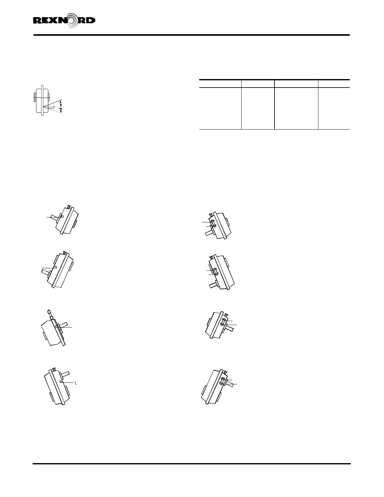
Standard Drive Mounting
Limits
The standard drive incline limits from the basic
3, 6, 9 & 12 o’clock mounting positions are
given in Section I, Page 4. For higher limits,
follow the instructions on Page 34 and the
drawings below. (6 o’clock illustrated)
CODE
C — Cap N — Nipple
E — Street Elbow P — Pipe Plug
L — Oil Level STD — No Modifications
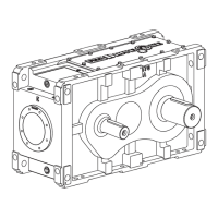
Horizontal Drive Modifications for Inclined H.S. Shaft
Standard Pipe Fittings
H
— Inches
.375-18 NPT Falk™ No. .500-14 NPT Falk™ No.
.375 Street Elbow 0915252 .500 Street Elbow 0915251
.375 Cap 0914802 .500 Cap 0914803
.375 x 1 Nipple 0915724 .500 x 1.12 Nipple 0915734
.375 x 1.5 Nipple 0915725 .500 x 1.5 Nipple 0915735
.375 x 2 Nipple 0915722 .500 x 2 Nipple 0915736
.375 x 3 Nipple 0915727 .500 x 2.5 Nipple 0915723
.500 x 3 Nipple 0915737
.500 x 4 Nipple 0915739
H
Kits: Falk™ Nos. 0786775 & 0786776 . . . Oil expansion chamber parts.
All pipe fittings are galvanized.
UP
DOWN
L — Always locate at high side plug.
KIT — Install at standard air vent location.
Shaft Mounted Drives Model A
Sizes 5107-5315 (Page 35 of 44)
 Loading...