Remove packing rings from the drive shaft and slide the
drive shaft through the seal housing. Install seal rings into
the seal housing. Stagger the seal joints approximately 90°
apart. Slip the compression ring into place. Use fasteners
with flat washers to hold the ring but DO NOT tighten at
this time. Install key in the drive shaft keyway and then
install the drive shaft into the hollow shaft. Use the thrust
plate fastener, Figure 7, to secure the drive shaft. Refer to
Table 3 for torque value. Use the seal housing fasteners to
secure the seal housing to the basic drive. Refer to Table 4
for the torque value. Reinstall the hollow shaft cover. To
adjust packing seal, rotate input shaft to test the
resistance. Tighten the compression ring fasteners evenly
until an additional resistance can be detected when the
high speed shaft is rotated. DO NOT OVERTIGHTEN -
this can cause premature seal wear and possible
overheating. Proceed to Step 5.
5. JSC — Fasten the trough end to the seal housing using the
hex head cap screws included in the drive shaft kit. Refer to
Table 4 for torque value. Proceed to Step 7.
6. JF — Install backstops prior to installation of the drive
(Refer to Appendix B). If an adapter flange is provided,
assemble it to the drive using fasteners provided with the
flange. Refer to Table 5 for fastener selection and torque
value. Remove the input side hollow shaft cover. The
standard method for connecting a flange mounted drive to
the driven shaft is to prepare the driven shaft per Appendix
H and mount the drive to the tapered shaft using a thrust
plate kit with fastener as shown in Table 3. An optional
method of connection should be used when replacing
existing drives with special shafts or when producing
tapered shafts is impractical. This optional method uses a
TA tapered bushing as outlined in Appendix J.
Installation
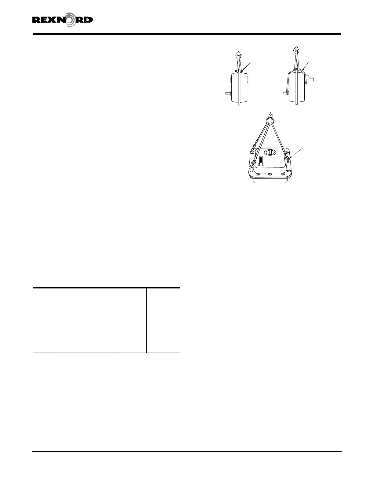
7. JR, JF & JSC — Refer to Figure 11 for recommended lifting
method. In order to sling JR & JF as illustrated, remove a
housing flange fastener and install a long fastener with nut. For
vertical installation, use (3) eye bolts as illustrated. Eyebolt sizes
are 5/16" for 5107 and 5115, 3/8" for 5203 and 1/2" for
5207 thru 5315. DO NOT remove sling until drive is secured
to shaft. Before lifting the drive into position, rotate the high
speed shaft until the hollow shaft keyway will be in position to
line-up with the driven shaft key. JF proceed to Step 12; JSC to
Step 13.
8. JR — If the drive was received with a backstop installed,
the backstop must be temporarily removed to facilitate
mounting.
Refer to Section II, Figure 19 and remove cover Ref.
#16 and backstop Ref. #5A1.
9. JR — Lift the drive into position and slide onto the drive
shaft taking care that the driven shaft key seats into the
hollow shaft keyway. DO NOT hammer or use excessive
force. Refer to Figure 12 for installation of the torque arm.
The exact position of the tie rod may vary within the range
shown. For torque arm mountings other than shown, refer
to Falk. If it is necessary to shorten the torque arm, cut the
excess from either threaded end.
The support to which the clevis bracket is to be fastened must
sustain the torque reaction shown in Table 8. The maximum
load reaction through the torque arm occurs when the
torque arm is located in the extreme (30°) off angle position.
Use Grade 5 fasteners to anchor the clevis bracket; see
Table 7 for the fastener diameter and tightening torque.
Bolt the tie rod to both the clevis bracket and the drive
anchor bracket and tighten the bolts until seated against the
brackets. DO NOT bend the bracket as clearance between
the clevis brackets and tie rod is necessary.
Rexnord Industries, LLC 3001 W. Canal St., Zip 53208-4200, Milwaukee, WI USA (PN-2128394) 378-200
Telephone: 414-342-3131 Fax: 414-937-4359 November 2010
e-mail: info@rexnord.com web: www.rexnord.com Supersedes 6-07
Shaft Mounted Drives Model A
Sizes 5107-5315 (Page 7 of 44)
TABLE 5 — Flange Mounted Drive – Foundation
Fastener Size & Tightening Torque
(Non-Lubricated Fasteners)
DRIVE
SIZE
Fastener Size and Grade
Torque
lb-ft (Nm)
Min Fastener
Engagement
Into Drive
Housing
Inches (mm)
5107 .500-13UNC, GR.5 69 (94) .76 (19,3)
5115 .625-11UNC, GR.5 137 (186) .94 (23,9)
5203 .750-10UNC, GR.5 245 (332) .76 (19,3)
5207 .875-9UNC, GR.5 380 (515) .88 (22,4)
5215 1.000-8UNC, GR .5 567 (769) 1.00 (25,4)
5307 1.000-8UNC, GR .8 792 (1074) 1.24 (31,5)
5315 1.000-8UNC, GR .8 792 (1074) 1.24 (31,5)
SLING FROM
LONG FASTENER
WITH NUT
SLING AROUND
SEAL HOUSING
AND INPUT SHAFT
Figure 11
SLING FROM
EYEBOLTS