Rotate high speed shaft in the required direction of rotation
and then reverse the rotation to lock up the backstop.
Observe the position of the sprags. All sprags must be
engaged and lay in the same relative position around the
shaft. If the sprags are not uniformly positioned, lightly tap
the backstop cage to centralize all the sprags around the
shaft and cage. If sprags cannot be uniformly positioned in
this manner, remove the backstop and run a finger around
the sprags in the overrunning direction. Reinstall backstop
as instructed in preceding steps.
Check the position of the sprags several times by
overrunning and locking the sprags. If all sprags move
uniformly, hold the backstop in the locked position and
proceed to the next assembly step.
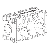
4. FINAL ASSEMBLY — EXTERNAL PARTS: On drive Sizes
5107J and 5115J, install one gasket Ref. #23, cover
spacer Ref. #17, spider Ref. #5A5, second gasket Ref.
#23, and backstop end cover Ref. #16 (Size 5115J uses
stamped end cover removed in Step 1). Oil feed slots in
gaskets and cover spacer must be aligned with the housing
backstop oil feed hole to provide proper lubrication for the
backstop. Refer to figures 3A and 3B. Install fasteners with
lock washers and cross tighten to 3.5 lb-ft (4,7 Nm)
torque.
On drive Sizes 5203 thru 5315, install one gasket Ref.
#23 and backstop end cover Ref. #27 to drive housing
(one gasket Ref. #23, cover spacer Ref. #17, second
gasket Ref. #23, and end cover Ref. #16 on drive Size
5207J). Size 5207J uses end cover and fasteners removed
in Step One. Oil feed holes or slots in gaskets, cover
spacer (5207J), and cast shaft covers must be aligned with
the housing backstop oil feed hole to provide proper
lubrication to the backstop. Install fasteners with lock
washers and cross tighten to 8 lb-ft (11 Nm) torque.
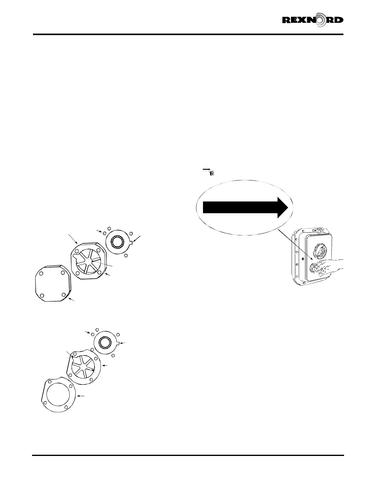
Clean housing surface for rotation and WARNING labels.
Affix the rotation indicator label next to the high speed
shaft extension to indicate the free direction of rotation
(Figure 4). Fill to oil level specified in Section I with oil
specified in Appendix A. Check motor for correct rotation
before completing connection to drive.
BACKSTOP REPLACEMENT — IN EXISTING DRIVES
WITH DAMAGED BACKSTOPS
5. DISASSEMBLY— EXTERNAL PARTS: Drain oil from drive
and remove backstop cover fasteners, backstop end cover,
gasket(s), cover spacer (where used), and spider (where
used). Save all metallic parts for possible reuse.
6. BACKSTOP REMOVAL: Remove backstop from drive and
discard, keep backstop key, backstop spacer (5115J25
only), and backstop retaining rings (where used) for
possible reuse. Remove housing spacer from drive housing
backstop bore and keep for reuse. NOTE: Complete drive
disassembly is required to replace the high speed shaft,
refer to Sections II and III of this manual for disassembly,
parts replacement, and reassembly of the basic drive.
7. BACKSTOP PREPARATION, BACKSTOP INSTALLATION
AND EXTERNAL PARTS ASSEMBLY: Refer to Sections 2,
3, and 4 of this appendix for preparation of the backstop,
installation of the backstop in the rebuilt drive, assembly of
the external parts associated with the backstop to the drive
and preparation of the drive for service.
Rexnord Industries, LLC 3001 W. Canal St., Milwaukee, WI 53208-4200 USA378-200 (PN-2128394)
Telephone: 414-342-3131 Fax: 414-937-4359November 2010
e-mail: info@rexnord.com web: www.rexnord.comSupersedes 6-07
Backstop Installation
DRIVE EQUIPPED
WITH INTERNAL BACKSTOP
H.S. SHAFT ROTATION
DO NOT USE EXTREME
PRESSURE LUBRICANTS
THE FALK CORPORATION
DRIVE EQUIPPED
WITH INTERNAL BACKSTOP
H.S. SHAFT ROTATION
DO NOT USE EXTREME
PRESSURE LUBRICANTS
THE FALK CORPORATION
Figure 4
Shaft Mounted Drives Model A
(Page 28 of 44) Sizes 5107-5315
BACKSTOP OIL
FEED HOLE
INSTALLED BACKSTOP
(WITH RETAINING
RING)
GASKET
END COVER REF.#16
SPIDER 5A5
EXTERNAL HOUSING
SPACER WITH GASKET
ON BOTH SIDES REF.#17
5107J WITH
BACKSTOP
Figure 3A
BACKSTOP OIL
FEED HOLE
INSTALLED BACKSTOP
(WITH SPACER AND
RETAINING RING
ON 5115J25)
OIL FEED
SLOT
EXTERNAL HOUSING SPACER
WITH GASKET ON BOTH SIDES
REF.#17
SPIDER 5A5
STAMPED ( REF.#16) END COVER
Figure 3B
5115J WITH BACKSTOP
 Loading...