a. THIN WALL BUSHING (with keyway slot through the
bushing wall) — With the driven shaft keyway at the 12
o’clock position, slide bushing assembly onto the driven
shaft, nut end first, and position the keyway slot over the
shaft keyway (the bushing may have to be pried open
slightly). Insert the drive, key furnished with the bushing,
into the shaft keyway. Proceed to Step 7.
b. THICK WALL BUSHING (with separate internal and
external keyways) — Insert the driven shaft key into the
driven shaft keyway. If the driven shaft has an open-ended
keyway, stake the keyway, Figure 4, to prevent axial
dislocation of the shaft key under operating conditions.
Slide the bushing assembly onto the driven shaft (the
bushing may have to be pried open slightly). Rotate the
shaft so the external keyway in the bushing is at the 12
o’clock position. Then insert the drive key, furnished with
the bushing, into the keyway. Proceed to Step 7.
4. JSC — NOTE: See Appendix K for non-tapered drive
shafts. Remove the hollow shaft cover from the input side of
the hollow shaft bore and save. Separate contents from the
drive shaft kit. Install thrust plate and retaining ring in the
hollow shaft, Figure 5. When the drive is a Size 5107 and
will employ a 2.437”(61,9 mm) or 3.000” (76,2 mm)
diameter drive shaft, place the (2) gaskets and trough end
spacer, packaged separately, over the trough end surface
of the seal housing, Figure 6. Continue outfitting based on
the type of trough end seal to be installed: (a) Waste
Packing Seal; (b) Lip Seal or; (c) Packing Gland Seal.
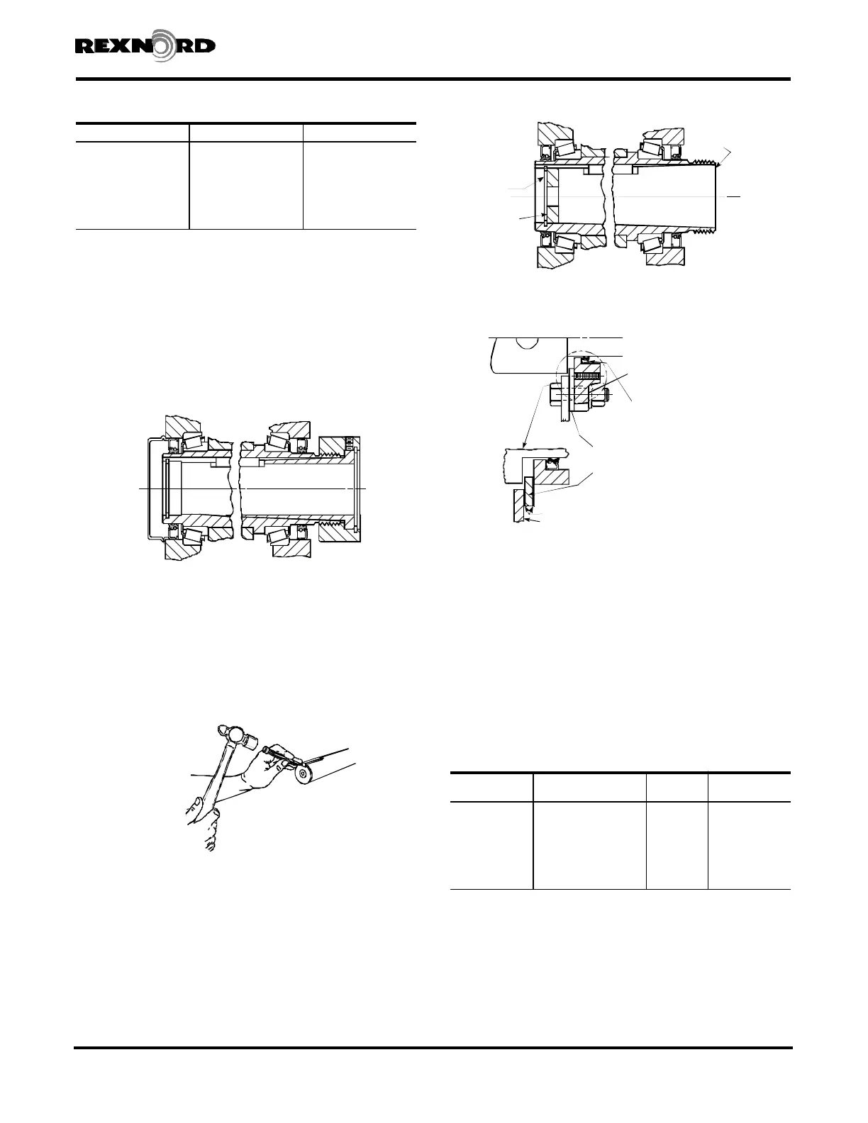
a. WASTE PACKING SEAL (Figure 7) — Slide drive shaft
thru seal housing. Insert key into drive shaft and slide
drive shaft into hollow shaft. The seal housing registers
into the basic drive seal bore. Install the drive shaft thrust
plate fastener thru thrust plate and torque to the value
specified in Table 3. Use the seal housing fasteners to
secure the seal housing to the basic drive housing. Refer
to Table 4 for proper torque value. Reinstall hollow shaft
cover. Pack seal housing with waste packing and
proceed to Step 5.
Rexnord Industries, LLC 3001 W. Canal St., Zip 53208-4200, Milwaukee, WI USA (PN-2128394) 378-200
Telephone: 414-342-3131 Fax: 414-937-4359 November 2010
e-mail: info@rexnord.com web: www.rexnord.com Supersedes 6-07
Shaft Mounted Drives Model A
Sizes 5107-5315 (Page 5 of 44)
TABLE 2 — N Dimension Inches (mm)
H
DRIVE SIZE Minimum Maximum
5107 5.00 (127) 7.19 (183)
5115 5.55 (141) 8.05 (204)
5203 5.53 (140) 7.78 (198)
5207 6.11 (155) 8.72 (221)
5215 7.08 (180) 10.15 (258)
5307 7.39 (188) 10.69 (272)
5315 7.92 (201) 10.74 (273)
H
The minimum engagement is necessary for full bushing engagement; the
maximum engagement is only required if a thrust plate will be employed to
remove the drive from the driven shaft.
H The minimum engagement is necessary for full bushing engagement; the
maximum engagement is only required if a thrust plate will be employed to
remove the drive from the driven shaft.
Figure 4
RETAINING
RING
THRUST
PLATE
HOLLOW
SHAFT
OUTPUT
SIDE
Figure 5
DRIVE
SHAFT
DRIVE SHAFT
GASKET
TROUGH END
MECHANICAL LIP SEAL
TROUGH END SPACER
(SIZE 4107 WITH 2.437" (61,9 mm)
& 3.000" (76,2 mm) DRIVE SHAFTS ONLY)
Figure 6
TABLE 3 — JF & JSC Thrust Plate Fastener
Data (Non-Lubricated Fasteners)
DRIVE SIZE Fastener Size & Grade
†
Torque
lb-ft (Nm)
Min. Thread Depth
Inches (mm)
5107 .500-13UNC x 3.25, GR. 8 92 (125) 2.00 (50,8)
5115 .500-13UNC x 3.25, GR. 8 92 (125) 2.00 (50,8)
5203 .625-11UNC x 3.50, GR. 8 183 (248) 2.00 (50,8)
5207 .625-11UNC x 3.50, GR. 8 183 (248) 2.00 (50,8)
5215 .875-9UNC x 3.50, GR. 8 533 (723) 2.50 (63,5)
5307 1.00-8UNC x 4.00. GR. 5
‡
567 (769) 2.75 (69,8)
5315 1.00-8UNC x 4.00. GR. 8 792 (1074) 2.75 (69,8)
†
Fastener lengths given are for applications using tapered drive shafts. Other
lengths may be needed for applications using tapered bushings.
‡
1.00-8UNC x 3.50, GR. 5 for 5307JF.