Form RZ-NA-I-FE/BE, Mfg P/N 98807 Rev 10, Page 11
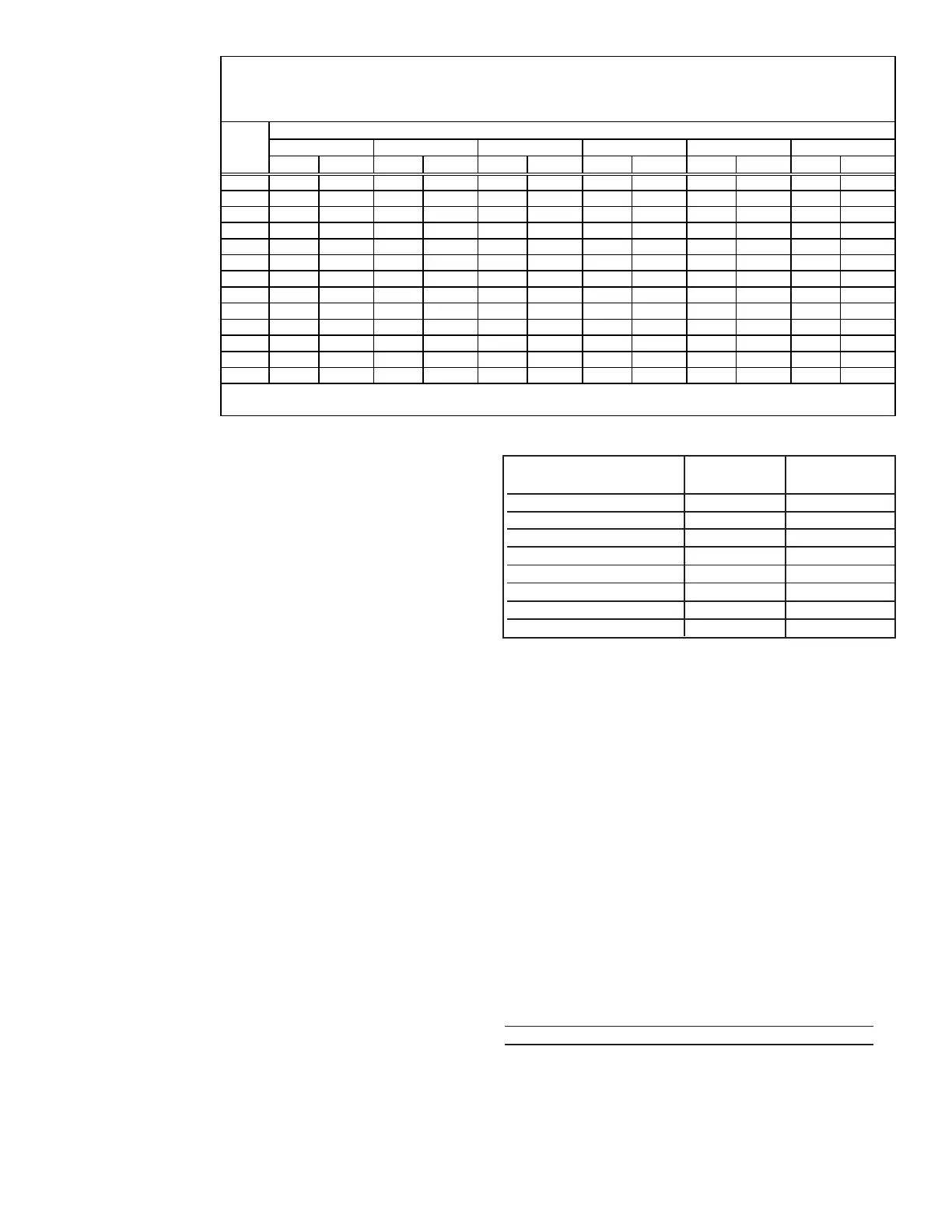
Sizing a Gas
Supply Line
Capacity of Piping
Cubic Feet per Hour based on 0.3" w.c. Pressure Drop
Specific Gravity for Natural Gas -- 0.6 (Natural Gas -- 1000 BTU/Cubic Ft)
Specific Gravity for Propane Gas -- 1.6 (Propane Gas -- 2550 BTU/Cubic Ft)
Length Diameter of Pipe
of 1/2" 3/4" 1" 1-1/4" 1-1/2" 2"
Pipe Natural Propane Natural Propane Natural Propane Natural Propane Natural Propane Natural Propane
20' 92 56 190 116 350 214 730 445 1100 671 2100 1281
30' 73 45 152 93 285 174 590 360 890 543 1650 1007
40' 63 38 130 79 245 149 500 305 760 464 1450 885
50' 56 34 115 70 215 131 440 268 670 409 1270 775
60' 50 31 105 64 195 119 400 244 610 372 1105 674
70' 46 28 96 59 180 110 370 226 560 342 1050 641
80' 43 26 90 55 170 104 350 214 530 323 990 604
90' 40 24 84 51 160 98 320 195 490 299 930 567
100' 38 23 79 48 150 92 305 186 460 281 870 531
125' 34 21 72 44 130 79 275 168 410 250 780 476
150' 31 19 64 39 120 73 250 153 380 232 710 433
175' 28 17 59 36 110 67 225 137 350 214 650 397
200' 26 16 55 34 100 61 210 128 320 195 610 372
Note: When sizing sup ply lines, consider p ossibilities of future expansion and increased requirements.
Refer to National Fuel Gas Code for additional information on line sizing.
Inlet supply pressure to the valve for propane gas must be a mini-
mum of 11" w.c. and a maximum of 14" w.c.
Before attempting to measure or adjust manifold gas pressure, the
inlet supply pressure must be within the specified range both when
the heater is in operation and on standby. Incorrect inlet pressure
could cause excessive manifold gas pressure immediately or at some
future time. If natural gas supply pressure is too high, install a
regulator in the supply line before it reaches the heater. If natural
gas supply pressure is too low, contact your gas supplier.
Instructions on How to Check Manifold
Pressure (can only be done after heater is
installed):
1) With the manual valve positioned to prevent flow to the main
burners, connect a manometer to the 1/8" pipe outlet pressure tap
in the valve. NOTE: A manometer (fluid-filled gauge) is recom-
mended rather than a spring type gauge due to the difficulty of
maintaining calibration of a spring type gauge.
2) Open the valve and operate the heater. Measure the gas pressure
to the manifold. Normally adjustments should not be necessary to
the factory preset regulator.
If adjustment is necessary, set pressure to correct settings by turn-
ing the regulator screw IN (clockwise) to increase pressure. Turn
regulator screw OUT (counterclockwise) to decrease pressure.
Derating by Manifold Pressure Adjustment
for High Altitude Operation
If the heater is being installed above 2000 ft (610M) and it was
determined in Paragraph 5 that derating by manifold pressure ad-
justment is permissible, follow the instructions below.
Instructions for Derating a Heater by Adjusting Manifold
Pressure (The heater must have a single-stage gas valve
and must be factory-equipped for sea level operation.)
1. Check the rating plate to be certain that the heater is equipped
for sea level operation. Do not attempt to derate by manifold gas
pressure adjustment if the heater is factory equipped for high
altitude. Do not attempt to adjust manifold pressure on heaters
equipped with two stage gas valves.
2. Determine the required manifold pressure for the elevation where
the heater will be operating. If unsure of the elevation, contact
the local gas supplier.
Manifold Pressure Settings by Elevation
Altitude Natural Gas Propane Gas
Feet Meters (inches W.C.) (inches W.C.)
0- 2000 1-610 3.5 10.0
2001-3000 911-915 2.8 7.7
3001-4000 916-1220 2.5 7.1
4001-5000 1221-1525 2.3 6.4
5001-6000 1526-1830 2.1 5.8
6001-7000 1831-2135 1.9 5.2
7001-8000 2136-2440 1.7 4.6
8001-9000 2441-2745 1.5 4.1
3. With the manual valve positioned to prevent flow to the main burners,
connect a manometer to the 1/8” pipe outlet pressure tap in the valve.
Use a fluid-filled manometer that is readable to the nearest tenth of an
inch w.c.
4. Remove the cap from the pressure adjusting screw and adjust the mani-
fold pressure to the pressure setting selected from the table. Cycle the
main burners once or twice to properly seat the adjustment spring in
the valve.
Re-check the pressure. If necessary, re-adjust the pressure. When the
pressure is correct, remove the manometer and replace the cap. Check
for leaks at the pressure tap fitting.
5. With the heater operating determine that the inlet pressure to the heater
for natural gas is between 5 and 14 inches w.c. and for propane between
10 and 14 inches w.c. Take this reading as close as possible to heater
(Most heaters are now equipped with gas valves that have an inlet
pressure tap.) If the inlet pressure is not within the specified range,
the inlet pressure must be corrected and Steps 3 and 4 repeated.
6. If altitude is above 6000 ft (1830M), verify that the pressure switch
has been changed.
High Altitude Combustion Air Pressure Switch
P/N Description
159180 #PPS10027-2733
7. Find the Manifold Pressure Adjustment label in the plastic bag that
contained these instructions. Using a permanent marker, fill-in the
pressure setting. Adhere the label on the heater near the gas valve so that
it is conspicuous to someone servicing the valve and /or heater.
 Loading...


