Form RZ-NA-I-FE/BE, Mfg P/N 98807 Rev 10, Page 5
5. High Altitude Operation
If the heater is being installed in an altitude above 2000 ft (610M),
check the rating plate to determine what must be done to prepare the
heater for high altitude operation.
NOTE: A heater equipped with a two-stage valve must be factory-
built for high altitude installation.
Check the rating plate, determine which circumstance below applies,
and follow the instructions.
• If the altitude range on the rating plate agrees with the altitude
at the site, no further action is required. Proceed with the instal-
lation.
• If the altitude range on the rating plate reads "Sea Level" and
the altitude at the site is between 2000 ft and 6000 ft (610M
to 1830M) and the heater has a single-stage gas valve, install
the heater and follow the instructions in Paragraph 11 to derate by
manifold gas pressure adjustment.
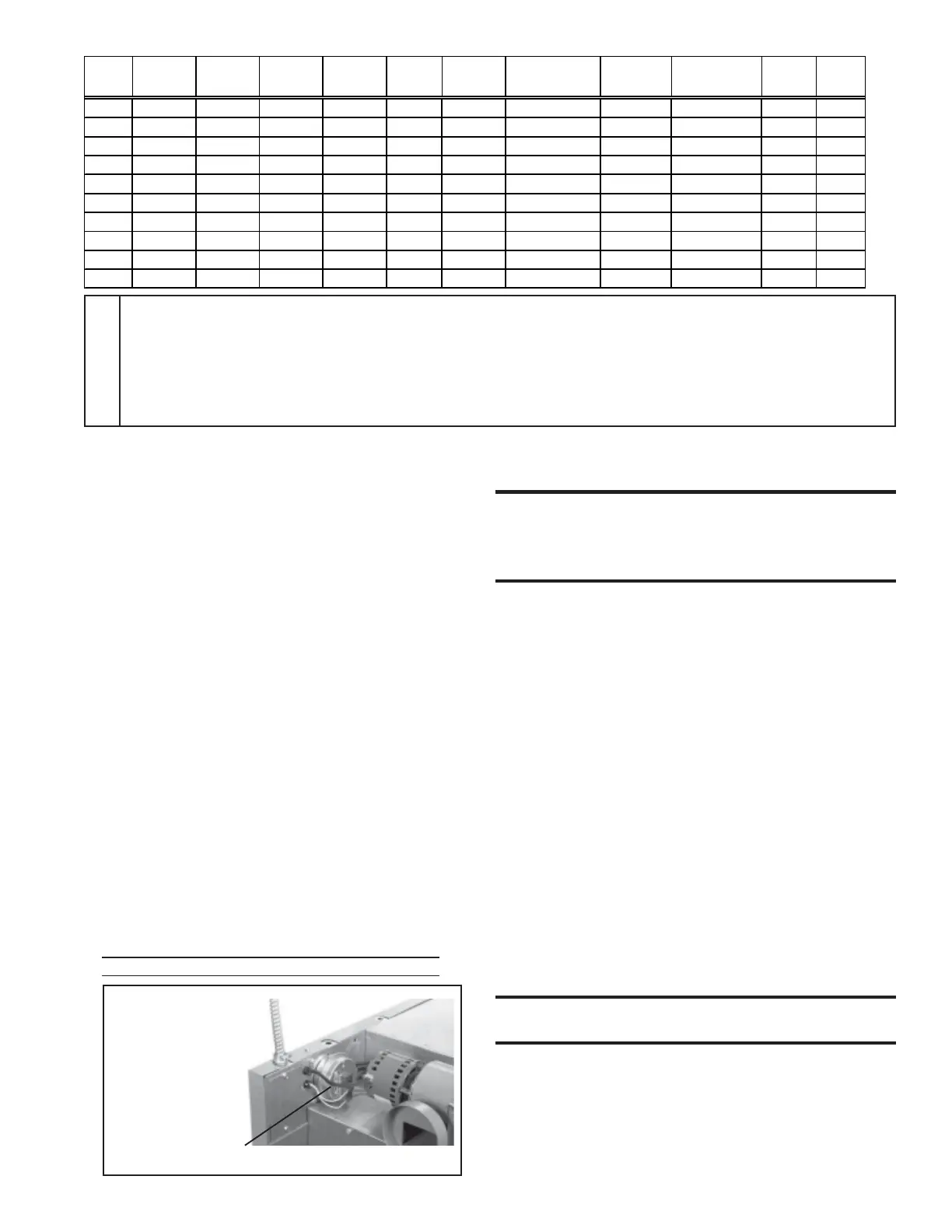
• If the altitude range on the rating plate reads "Sea Level" and
the altitude at the site is above 6000 ft (1830M) and the
heater has a single-stage gas valve, in addition to adjusting the
manifold pressure, it will be necessary to replace the combustion
air pressure switch. Order the listed below and replace the switch
before suspending the heater.
After the heater is installed, follow the instructions in Paragraph
11 to derate by adjusting the manifold gas pressure.
High Altitude Combustion Air Pressure Switch
P/N Description
159180 #PPS10027-2733
E
Use with 4-point suspension with blower cabinet.
F
Contactor is standard on Models 300 and 400; optional on other
sizes.
G
Contactor location with optional three phase motors on Sizes 50,
75, 100 and 125.
H
Deduct 6-5/8" (168mm) on Sizes 50, 75, and 100 when equipped
with direct drive motor.
NOTES
A
When equipped with optional blower cabinet.
B
When equipped with optional duct flange.
C
Dimension includes a 3/4" flange on the rear of the blower
cabinet.
D
Use with 4-point suspension without blower cabinet. If
installing hanger kit Option CK19, suspension points
change; see Paragraph 9.
Size
M
A
N
A
P
A
R
A
S
B
T
B
U
A
W
A
X
E
YZ
Hanger
25
94 532 481 133 273 214 375 157 793 249 76
50
94 532 481 133 273 214 375 157 793 249 76
75
69 532 481 133 324 214 375 157 793 265 76
100
44 532 481 133 375 214 375 157 793 265 76
125
34 532 481 133 521 214 521 157 908 294 67
165
72 659 641 184 445 291 521 202 932 297 117
200
34 659 641 184 521 291 521 202 932 297 117
250
150 1030 641 184 660 291 660 202 932 297 117
300
150 1030 641 184 660 291 660 202 932 297 91
400
172 1284 641 184 870 291 870 202 932 297 91
6. Unit Heater Location
CAUTION: Avoid installing a unit heater in
extremely drafty areas. Extreme drafts can shorten
the life of the heat exchanger and/or cause safety
problems.
For best results, the heater should be placed with certain rules in mind. In
general, a unit should be located from 8 to 12 feet (2.4-3.7M) above the
floor. Units should always be arranged to blow toward or along exposed
wall surfaces, if possible. Where two or more units are installed in the
same room, a general scheme of air circulation should be maintained for
best results.
Suspended heaters are most effective when located as close to the work-
ing zone as possible, and this fact should be kept in mind when determin-
ing the mounting heights to be used. However, care should be exercised to
avoid directing the discharged air directly on the room occupants.
Partitions, columns, counters, or other obstructions should be taken into
consideration when locating the unit heater so that a minimum quantity of
airflow will be deflected by such obstacles.
When units are located in the center of the space to be heated, the air
should be discharged toward the exposed walls. In large areas, units should
be located to discharge air along exposed walls with extra units provided
to discharge air in toward the center of the area.
At those points where infiltration of cold air is excessive, such as at
entrance doors and shipping doors, it is desirable to locate the unit so that
it will discharge directly toward the source of cold air from a distance of
15 to 20 feet (4.6-6.1M).
Units should not be installed closer than 18 inches (457mm) from any
wall.
CAUTION: Do not locate the heater where it may
be exposed to water spray, rain or dripping water.
Figure 2-
Pressure Switch
Location (above
6000 ft, replace
with a pressure
switch set for high
altitude operation)
Pressure Switch
 Loading...


