Form I-MAPSIII&IV, P/N 222917R9, Page 29
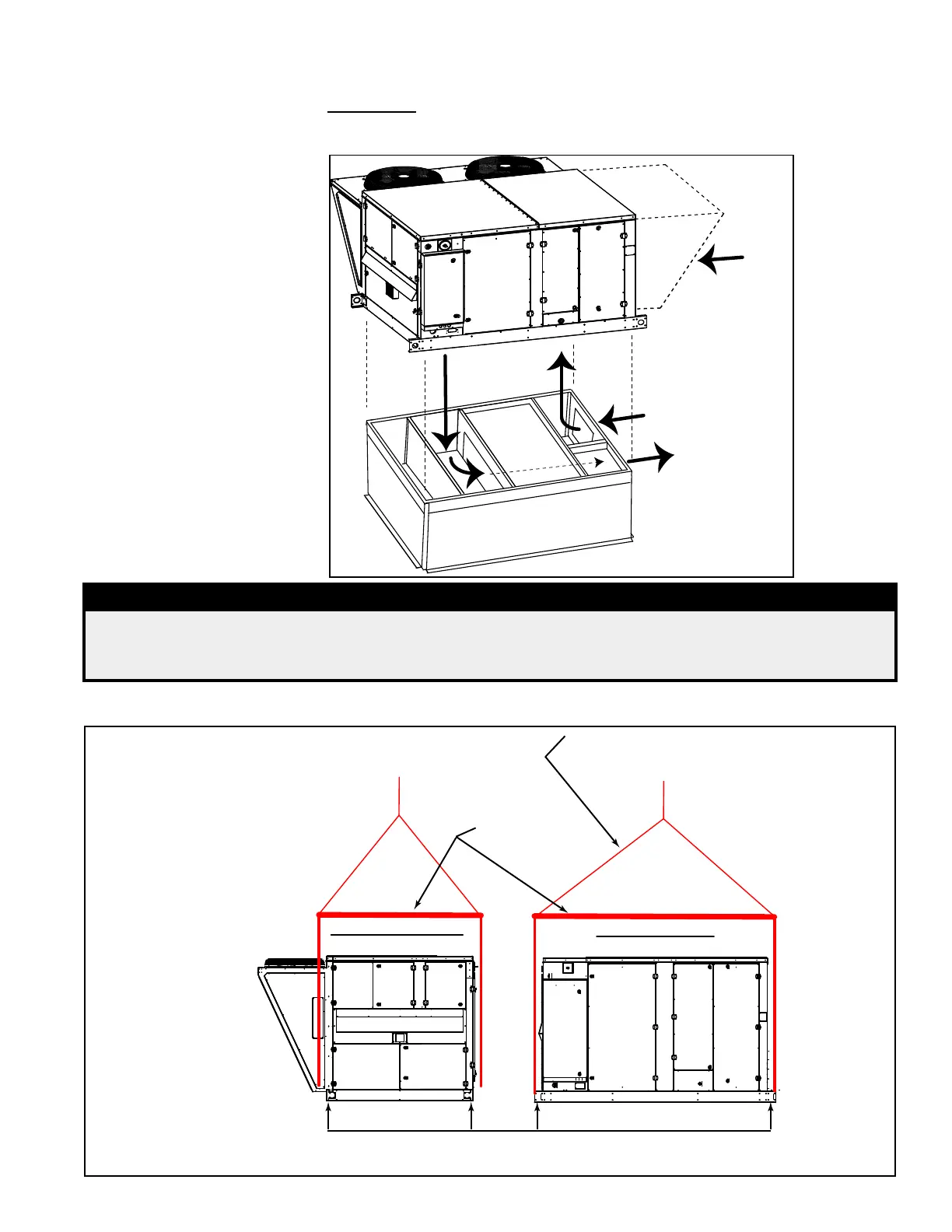
FIGURE 13 - Correct
Orientation when
Lifting to a Horizontal
Curb is with the Inlet
End of the MAPS
®
Unit
at the Duct Connection
End of the Roof Curb
Supply
(Discharge)
Air
Optional
Return Air
Outside
Inlet Air
Option CJ50, Horizontal Curb
(same orientation for CJ49)
MAPS
Cabinet B
Outside Air Hood is
installed after the
unit is set on the curb.
NOTE: If the installation
includes an energy
recovery module, install
the unit rst, placing it
in this same orientation
on the end of the
curb without the duct
connections.
□ If setting on the roof curb or a duct furnace curb section, verify that sealant tape is
applied to all top surfaces.
□ IMPORTANT: Verify that the lift operator knows the correct placement of the unit
so that the airow orientation will be correct. When placing a unit on a horizontal
ow curb, be sure the unit is being positioned as illustrated in FIGURE 13.
DANGER
To prevent death, injury, or equipment damage caused by inadequate or improper rigging,
test lift the unit before attempting to install it on the roof. To prevent injury, death, or
equipment damage when lifting, use ALL lifting points.
Test lift the unit to be sure that it is secure and the weight is balanced. Lift the unit slowly, following safe lifting proce-
dures.
Discharge End View
Control Side View
MAPS A, B, or C Cabinet
MAPS A, B, or C Cabinet
Spreader bars
are REQUIRED.
Four Lifting Points - one at each corner.
Lift straight up with vertical force only.
After test lift, adjust cable length as
needed so that the unit will remain
horizontal throughout the lift.
FIGURE 14A - Rigging and
Lifting a MAPS
®
A, B, or C
Cabinet using four lifting
points and spreader bars