Form I-MAPSIII&IV, Page 50
Senses Option Components Installation and Function
External DDC Controller, 0-5V VFC2 Requires a eld supplied input source.
Duct Static Pressure (0 to 2.5"
w.c.)
VFC3 Transducer, P/N
234818; Probe
P/N 234821
Factory installed to monitor duct pressure. Requires eld installation
of sensor in the supply duct. See instructions below and in the
sensor manufacturer's installation form.
Building Static Pressure
(-0.5 to 0.5" w.c.)
VFC4 Transducer, P/N
234819
Field installed sensor to monitor building pressure. Requires eld
installation of tubing and sensor. See instructions below and in the
sensor manufacturer's installation form.
CO2 Sensor (0-2000 ppm) VFC5 P/N 234820 Field installed in the building to monitor the carbon dioxide level. See
instructions below and in the sensor manufacturer's instructions.
Wall Stat for Low/Medium/High
Speed Control
VFC7 Requires CL77
wall sensor.
Wall temperature sensor, P/N 222756, must be installed. See the
wiring connections below and on the unit wiring diagram.
Four speed fan control VFC8 Factory installed relay. Two hardware inputs and four setpoints
provide 4-speed control through IQ controller.
Adjustable Constant Volume
Control
VFC9 Adjustable constant speed controlled by the IQ controller through an
adjustable setpoint.
8.0 Controls
(cont'd)
Sensors for Optional Variable Frequency Drive
8.1.2 Optional Unit Monitoring Sensors (cont'd)
8.1 Cooling/ Dehumidication/Heating Control (cont'd)
Field-installed Sensors
for VFC Options.
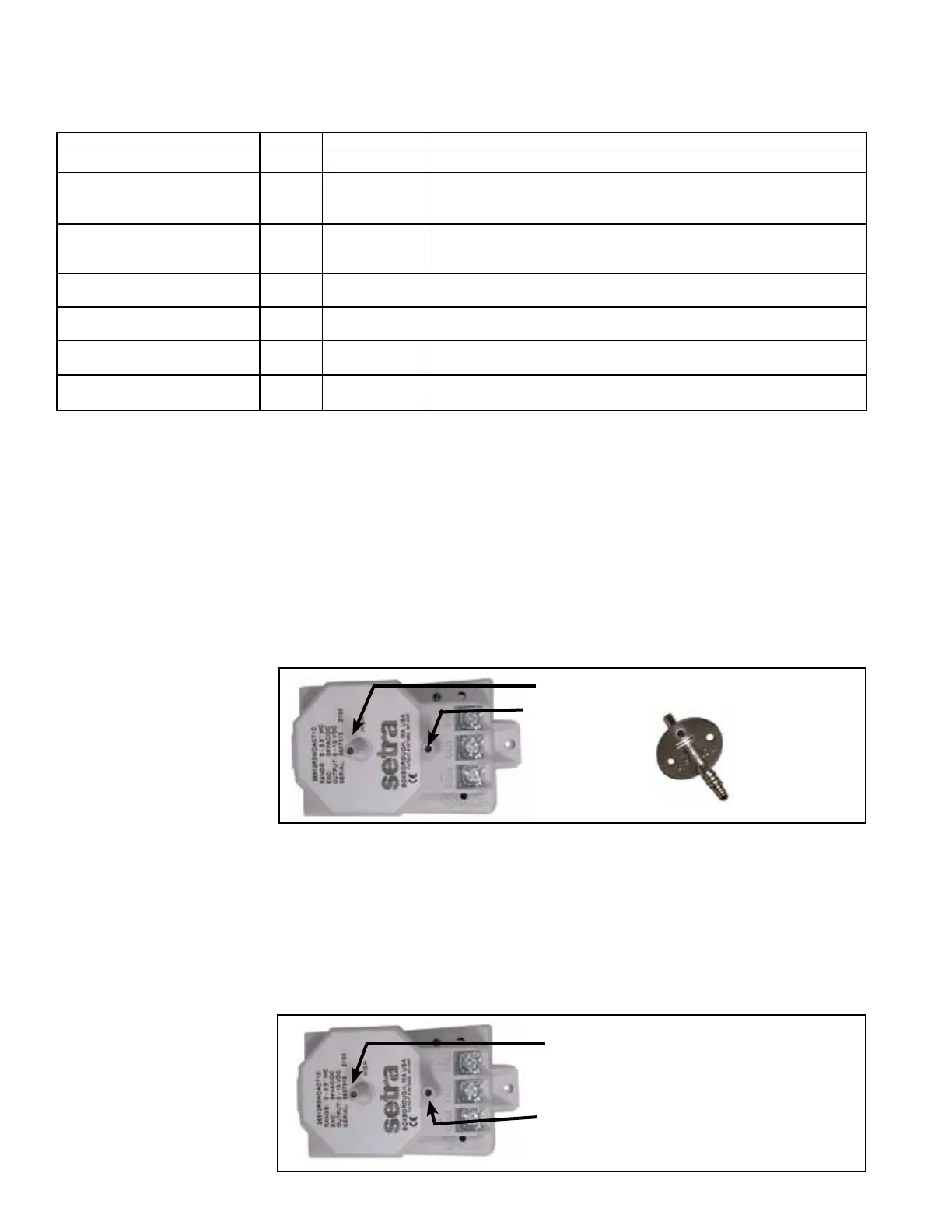
Option VFC3, Duct Static Pressure Sensor
The differential pressure transducer (P/N 234818) is mounted in the low voltage com-
partment. A data sensor pickup is shipped loose to be attached to the side of the duct-
work. To install the duct sensor port, locate a position about 2/3 the distance of the duct
run (minimum of 10 duct lengths). Drill a hole in the side of the duct, insert the sensor
tube and attach with sheetmetal screws. The transducer has a high and a low tubing
port. In most installations, the low tubing port will be sensing atmospheric pressure so it
can be left open. If a different reference point is needed, attach 1/4" tubing and extend
to that location. Connect 1/4" eld-supplied tubing to the high pressure port and to the
eld-installed sensor port. The transducer has a range of 0 to 2.5" w.c. and was cali-
brated at the factory; it should not need eld adjustment. Refer to the manufacturer's
instructions in the owner's envelope for additional information.
FIGURE 29A -
Tubing Ports on the
Transducer in Option
VFC3 and Ductwork
Sensor Port
High Pressure Port - Attach tubing.
Low Pressure
Port -
Leave open.
or attach
tubing.
High Pressure
Data Sensor Port
- Attach to duct-
work. Slide tubing
on barb.
Option VFC4, Building
Static Pressure Sensor
FIGURE 29B -
Electrical Connections
and Tubing Ports on
Option VFC4, Building
Static Pressure Sensor
High Pressure Port - Connect to the
high pressure reference point.
Low Pressure Port - Connect to the
low pressure reference point.
The differential pressure transducer (P/N 234819) used in Option VFC4 is mounted
in the low voltage compartment. The transducer has a high and a low tubing port.
Depending on the application, attach tubing to both ports or leave one open to atmo-
spheric pressure. Connect 1/4" eld-supplied tubing to the port(s) and run it to the
pressure reference point(s). Cut the end of the tubing at a 45° angle to minimize the
affect of air movement and attach it to a wall or in a ceiling. The transducer has a range
of -0.5 to .5" w.c. and was calibrated at the factory; it should not need eld adjustment.
Refer to the manufacturer's instructions in the owner's envelope for additional informa-
tion.