Form I-MAPSIII&IV, P/N 222917R9, Page 59
1) Turn the manual gas valve off. On the single-stage gas valve (either regular valve
in FIGURE 41A or dual valve in FIGURE 41B), locate the 1/8” output pressure tap(s).
Connect separate manometers to both 1/8" pipe outlet pressure taps in the valve.
NOTE: A manometer (uid-lled gauge) is recommended rather than a spring type
gauge due to the difculty of maintaining calibration of a spring type gauge.
2) Turn on the manual gas valve. Operate the unit with a call for heat. Check the
outlet pressure with burner at full re.
3) If adjustment is necessary, remove the cap(s) from the adjustment screw(s). Set
pressures to correct setting by turning the regulator screws IN (clockwise) to increase
pressure. Turn regulator screws OUT (counterclockwise) to decrease pressure.
After an adjustment is made, cycle the heat section. Re-check the outlet pressures of
the valve. When checking a dual valve, make sure that the outlet pressure is the
same at both taps.
When outlet pressures are correct for the installation, remove the manometers and
replace the caps. Check for leaks at the pressure tap ttings.
Follow the instructions below to check the valve outlet pressure and make necessary
adjustment. NOTE: Valve outlet pressure is also checked at high re.
Measure the Full Fire
Outlet Pressure of the
Single-Stage Valve(s)
- (can only be done
after heat section is
operating)
Remove the bushing and connect a manometer to each 1/8" pressure tap. NOTE: A
manometer (uid-lled gauge) is recommended rather than a spring type gauge due
to the difculty of maintaining calibration.
2) Turn on the manual gas valve. Operate the unit with a call for heat. With the
burner at full re, check the manifold pressure.
At sea level, the manifold pressure should be 3.5" w.c.
Be certain the actuator has fully opened the ball valve. This can be veried by the
position indicators on top of the actuator (FIGURE 40).
3) In most cases the manifold pressure will be correct and adjustment will not be
required. Replace the ttings and check for leaks.
In the rare instance that adjustment is required, the adjustment is made at the single-
stage gas valve. Continue with the instructions below for adjusting valve outlet
pressure.
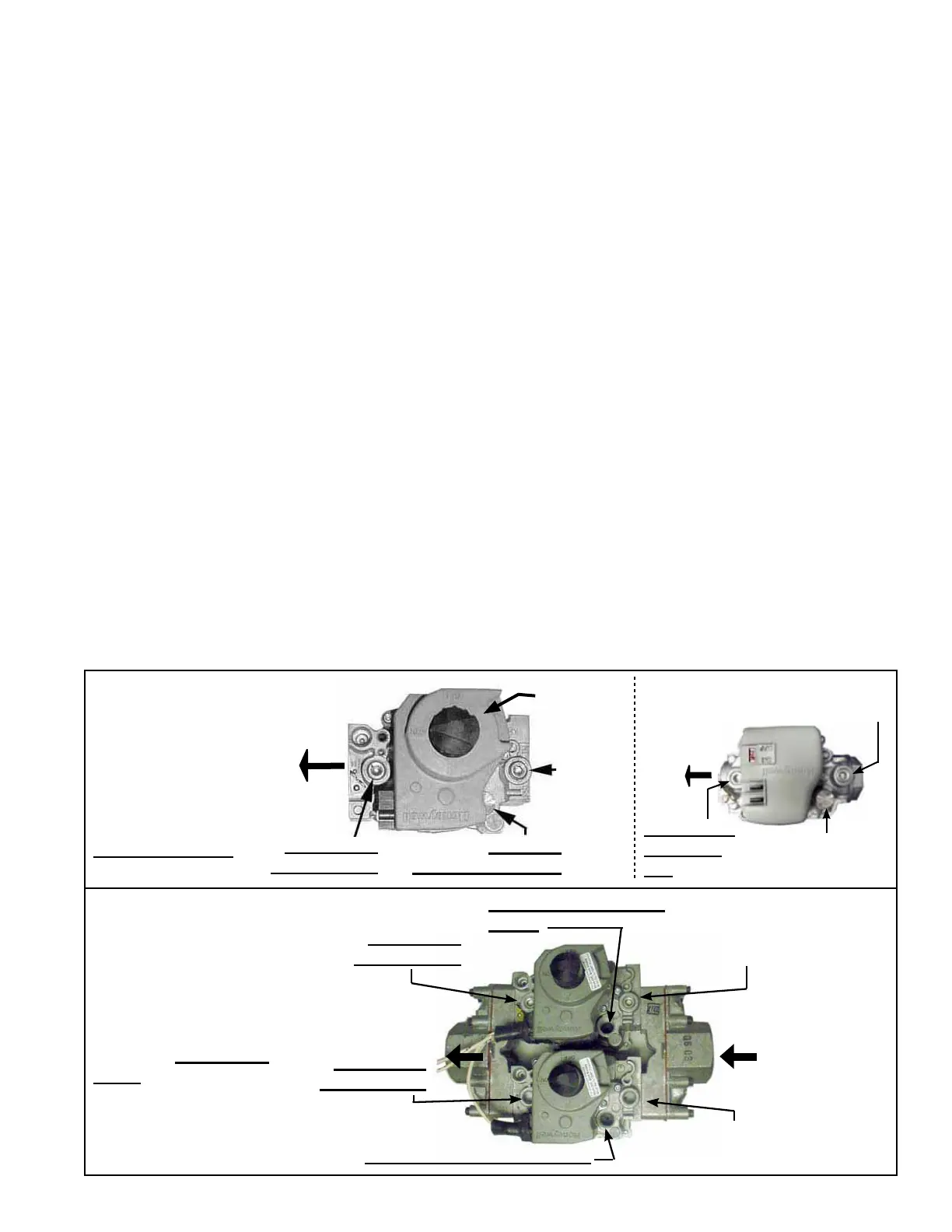
FIGURE 41A -
Outlet Pressure Tap
and Adjustment
Location on Single-
Stage, Valve (two
styles) used on
Heat Sections 100
- 300 in MAPS
®
Cabinets A and B
1/8” Output
Pressure Tap
Inlet
Pressure
Tap
Pressure
Adjustment Screw
Manual
Gas Valve
FIGURE 41B - Outlet
Pressure Taps
and Adjustment
Locations on Dual
Single-Stage,
Valve used on Heat
Sections 400 - 1600
in MAPS
®
Cabinets C
and D
1/8” Output
Pressure Tap
Inlet Pressure
Tap
Inlet Pressure
Tap
1/8” Output
Pressure Tap
Pressure Adjustment
Screw
Minimum inlet
pressure is
6" w.c.
Pressure Adjustment Screw
1/8” Outlet
Pressure
Tap
Inlet Pressure
Tap
Adjust Outlet
Pressure