1307SDH_RDH--EN,page 11/32
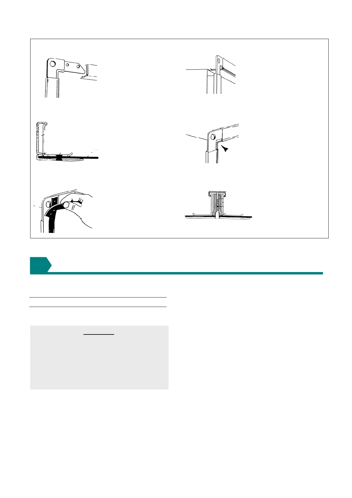
Figure 5 : Recommended procedure and method for connection of ducting and transitions to the air heaters using
a typical proprietary flange system.
1 Corner jointing framework
2 Cleats between sections to be joined
3 Fastening through all members
4 Checking alignment and joint worthiness
5 Applying gasket seals to prevent air leakage
6 Sectional view of completed joint
COMBUSTION AIR SUPPLY & FLUE SYSTEM
THIS SECTION ONLY APPLIES TO SDH models
6.1 General
6.1.1 Flue requirements
IMPORTANT
The flue must be installed in accordance with
national and local regulations. Failure to provide
proper flueing could result in death, serious
injury and/or property damage. The air heater
must be installed with a flue to the outside of the
building. Safe operation of any power vented gas
apparatus requires a properly operating flue
system, correct provision for combustion air and
regular maintenance and inspection.
Model SDH heaters may be installed as Type-B and
Type-C installations.
Flue must be in accordance with BS6230 or BS5440.
Local requirements may apply in addition to national
requirements. These unit heaters are designed to
operate safely and efficiently with either a horizontal or
vertical flue system when installed with the specific
requirements and instructions.
If this heater is replacing an existing heater, be sure that
the flue is sized properly for the heater being installed
and that the existing flue is in good condition.
A properly sized flue system is required for safe
operation of the heater. An improperly sized flue system
can cause unsafe conditions and/or create condensation.
The air heaters may be installed as a balanced flue (type
C) heater requiring both a combustion air inlet duct and a
flue pipe or as a power vented heater (type B) (the
combustion air is taken from the space where heater is
installed), which requires only a flue pipe exhausting to
outdoors.
All products of combustion must be flued to outdoor
atmosphere. Each heater installed as a type B appliance
must be fitted with an individual flue pipe and the
combustion air inlet opening must be provided with a
protection grill.
6
Cut and assemble flange
into frame to suit opening
Check dimensions and
position on duct spigot.
Ensuring flange is mated
correctly before fastening.
Checking location after
positioning.
 Loading...
