1307SDH_RDH--EN,page 28/32
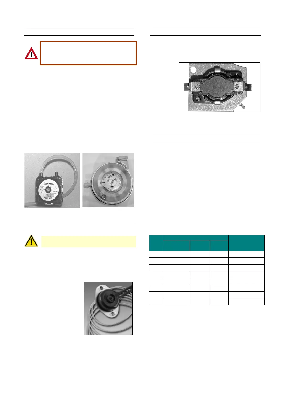
12.9 Combustion air pressure switch
Safe operation of this unit requires proper
venting flow. Never bypass the
combustion air pressure switch or attempt
to operate the unit without the venter
opera ting.
The combustion air pressure switch ensures that proper
combustion airflow is available. The switch senses the
differential pressure between the negative pressure in
the flue gas collector box and the pressure in the control
section. (For switch location, see figure 16).
On startup when the heater is cold, the sensing pressure
is at the most negative level, and as the heater and flue
system warm up, the sensing pressure becomes less
negative.
If a restriction or excessive flue pipe length causes the
sensing pressure to be below the allowable level, the
pressure switch will shut off the main burner.
If it is determined that the pressure switch needs
replacing, use only the factory-authorized replacement
part that is designed for the model and size of heater
being serviced.
Figure 33 : pressure switch
025-055: PN 30 60607 56 073-100:PN 30 60615
12.10 Limit controls
Never bypass the limit controls, hazardous
conditions could result
All units are equipped with a temperature activated limit
control. The control is factory set and non-adjustable. If
either set point is reached, the limit control will interrupt
the electric power to the gas valve. This safety device
provides protection in the case of motor failure or lack of
airflow due to restrictions (for location, see figure 16).
Figure 34
PN 03 25959 01
(025, 030, 035, 073)
PN 03 25959 02
(043, 055, 100)
12.11 Fan delay relay
In case of a not continuous running fan, the fan delay
relay will activate the blower fan motor maximum 60
seconds after the gas valve has opened. The fan will
stop after maximum 120 seconds after the gas valve has
shut down.
Figure 35 :
12.12 Flue and combustion air piping
Check the complete system at least once a year.
Inspection should include all joints, seams, concentric
adapters and the flue terminal cap. Replace any
defective or heavily corroded parts.
12.13 Air filters
SDH/RDH units have an optional facility for air intake
filters. Standard racks are provided to accommodate
50mm nominal thickness filter elements. Unless
otherwise specified, filters supplied will be expendable
type synthetic pleated elements. The sizes and
quantities required to suit individual appliances are
listed in table 8.
Table 8 : Filter size & quantities schedule
Qty required
Length
(mm)
Width
(mm)
025
2 496 395 60 61038 395496
030 4 496 395 60 61038 395496
035 4 496 395 60 61038 395496
043 4 496 395 60 61038 395496
055 4 496 395 60 61038 395496
073 6 496 395 60 61038 395496
4 496 395 60 61038 395496
2 624 496 60 61038 496624
100
Filter dimensions
SDH
RDH
Reznor PN
 Loading...
