I-RPB (04-21) 131782-A, Page 9
Gas Supply
Entrance
5
-3/4
(146mm)
Condensate
Weep Holes
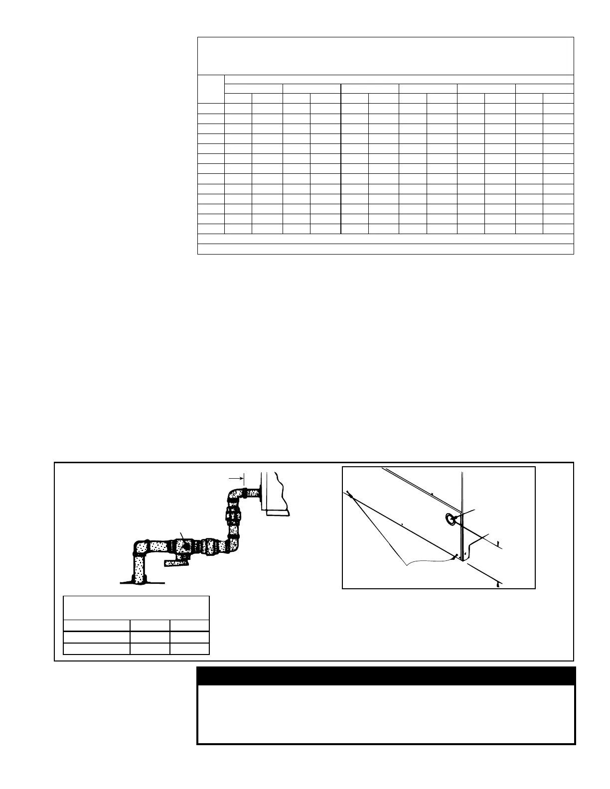
Install the gas supply piping so that when
the union is disconnected, the supply pipe
will not interfere with the removal of the
burner rack. The burner rack slides out of
the control side of the furnace.
FIGURE 5 - Gas Connection Location and Requirements
Gas Connection to Single-Stage
Valve (Not Gas Supply Line Size)
RPB 125-250 300-400
Natural Gas 1/2" 3/4"
Propane 1/2" 1/2"
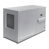
Gas Supply Sizing
Capacity of Piping
Cubic Feet per Hour based on 0.3 IN WC Pressure Drop
Specic Gravity for Natural Gas -- 0.6 (Natural Gas -- 1000 BTU/Cubic Ft)
Specic Gravity for Propane Gas -- 1.6 (Propane Gas -- 2550 BTU/Cubic Ft)
Length Diameter of Pipe
of 1/2" 3/4" 1" 1-1/4" 1-1/2" 2"
Pipe Natural Propane Natural Propane Natural Propane Natural Propane Natural Propane Natural Propane
20' 92 56 190 116 350 214 730 445 1100 671 2100 1281
30' 73 45 152 93 285 174 590 360 890 543 1650 1007
40' 63 38 130 79 245 149 500 305 760 464 1450 885
50' 56 34 115 70 215 131 440 268 670 409 1270 775
60' 50 31 105 64 195 119 400 244 610 372 1105 674
70' 46 28 96 59 180 110 370 226 560 342 1050 641
80' 43 26 90 55 170 104 350 214 530 323 990 604
90' 40 24 84 51 160 98 320 195 490 299 930 567
100' 38 23 79 48 150 92 305 186 460 281 870 531
125' 34 21 72 44 130 79 275 168 410 250 780 476
150' 31 19 64 39 120 73 250 153 380 232 710 433
175' 28 17 59 36 110 67 225 137 350 214 650 397
200' 26 16 55 34 100 61 210 128 320 195 610 372
Note: When sizing supply lines, consider possibilities of future expansion and increased requirements.
Refer to National Fuel Gas Code for additional information on line sizing.
Duct furnaces for natural gas are oriced for operation with gas having a heating value
of 1,000 (±50) BTU per cubic ft. If the gas at the installation does not meet this speci-
cation, consult the factory for proper oricing.
Pipe joint compounds (pipe dope) shall be resistant to the action of liqueed
petroleum gas or any other chemical constituents of the gas being supplied.
Install a ground joint union and manual shuto valve upstream of the unit control sys-
tem, as shown in FIGURE 5. The 1/8" plugged tapping in the shuto valve provides
connection for supply line pressure test gauge. The National Fuel Gas Code requires
the installation of a trap with a minimum 3" drip leg. Local codes may require a mini-
mum drip leg longer than 3" (typically 6").
After all connections are made, disconnect the pilot supply at the control valve and
bleed the system of air. Reconnect the pilot line and leak-test all connections by brush-
ing on a soap solution.
DANGER
All components of a gas supply system must be leak tested prior
to placing equipment in service. NEVER TEST FOR LEAKS WITH
AN OPEN FLAME. Failure to comply could result in personal
injury, property damage, or death.
 Loading...
