- Use of the amplifier with an incorrect band filter selected, or without a well-
adjusted antenna, may damage the amplifier.
12 K3 ELECRAFT™ TRANSCEIVER CONTROL CABLE SCHEMATIC
DIAGRAM
This section explains the electrical connections to control the amplifier with a K3 ELECRAFT™
transceiver provided of D-SUBHD (15 pin) “ACC” connector.
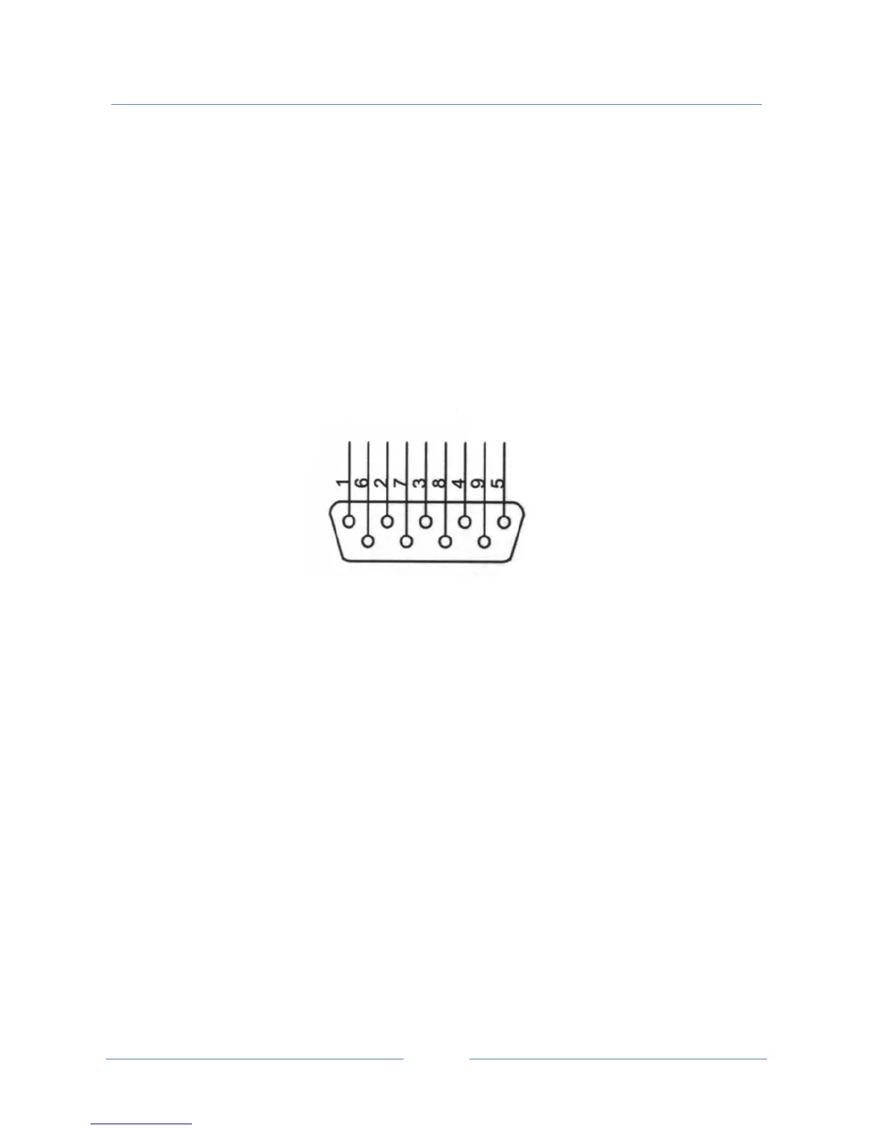
“ AUTO B” D-SUB (9 pin) male connector
NOTE: as viewed from rear panel
D-SUB (9 pin) NR. : CONNECT TO K3 ELECRAFT™ ACC CONNECTOR NAMED:
1 BAND0 OUT
2 BAND1 OUT
3 BAND2 OUT
4 BAND3 OUT
5 N.C.
6 KEYOUT-LP
7 N.C.
8 N.C.
9 GROUND
Note: as cable use a five wire plus shield quality shielded cable.


 To Next Page