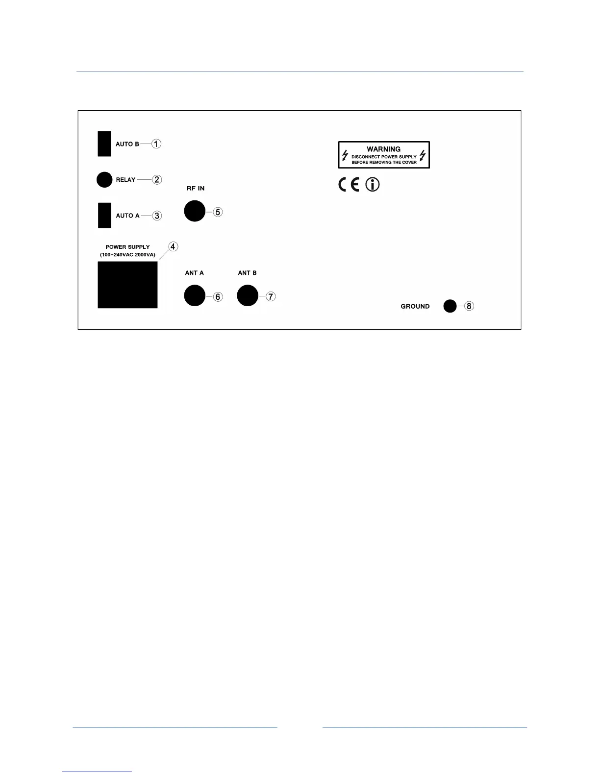
4 REAR PANEL DESCRIPTION
1 AUTO B
D-SUB (9 pin) male connector for control cable from ICOM™ - YAESU™- ELECRAFT™ transceiver.
2 RELAY (Opto-Isolated input)
RCA female connector for control cable from KENWOOD™ transceiver (or other brand). The center
pin is to be shorted to ground through the relay circuit of the transceiver; the total keying current
is under 10 mA.
Note: when you use this connector with no KENWOOD™ transceiver, the amplifier will
not be operative in auto mode.
3 AUTO A
D-SUB (9 pin) male connector for control cable from KENWOOD™ RS-232 COM port transceiver.
4 POWER SUPPLY
IEC type C14 AC Mains Socket. Socket for the AC power cord with two 10A (5x20 fast type) fuses
included (socket is EMI filtered).
5 RF IN
Amphenol™ SO-239 RF input connector. Connect the coax jumper cable from the transceiver.
6 ANT A
Amphenol™ SO-239 primary RF output connector. Connect the coax cable to the primary antenna.
7 ANT B
Amphenol™ SO-239 second RF output connector. Connect the coaxial cable to the second antenna
or a dummy load.
8 GROUND
Ground terminal.



 To Next Page