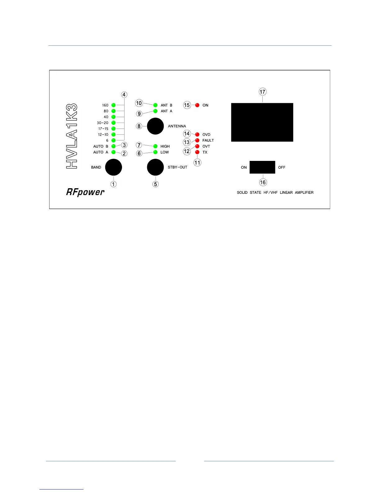
3 FRONT PANEL DESCRIPTION
1 BAND
This 9 position rotary switch select the manual (green LEDs “AUTO A” and “AUTO B” unlit) or auto
desired operating frequency band.
2 AUTO A
Green LED lights when operating frequency band is automatically controlled by KENWOOD™
transceiver; if not, the manual operating frequency band has been chosen.
3 AUTO B
Green LED lights when operating frequency band is automatically controlled by ICOM™ - YAESU™
or ELECRAFT™ transceiver; if not, the manual operating frequency band has been chosen.
4 160-80-40-30/20-17/15-12/10-6
Green LED lights according to the desired operating frequency band both for auto or manual
operating frequency band selection.
5 STBY – OUT
This 3 position rotary switch set in standby the amplifier in addition to set, the RF output power,
in intermediate or high level. The amplifier is in standby mode (amp ON but not operating) when
the green LEDs, marked “LOW” and “HIGH”, are OFF.
6 LOW
Green LED lights when intermediate RF output power level has been chosen; if not, the amplifier is
in standby mode.



 To Next Page