2.7 READER CONNECTIONS
On the Model 2022E, wiring should be fed through the cable gland and connected to the angle entry
terminal strip (TB1) on the circuit card. Wiring should be connected in accordance with the following:
TABLE 2-3 READER CONNECTIONS
TERMINAL STRIP (TB1) NOMENCLATURE CONNECTION
1 SIG SIG on Reader
2 SIG SIG on Reader
3 SHD NO CONNECTION IF
CONNECTED ON
READER
4 EN EN on Reader
5 EN EN on Reader
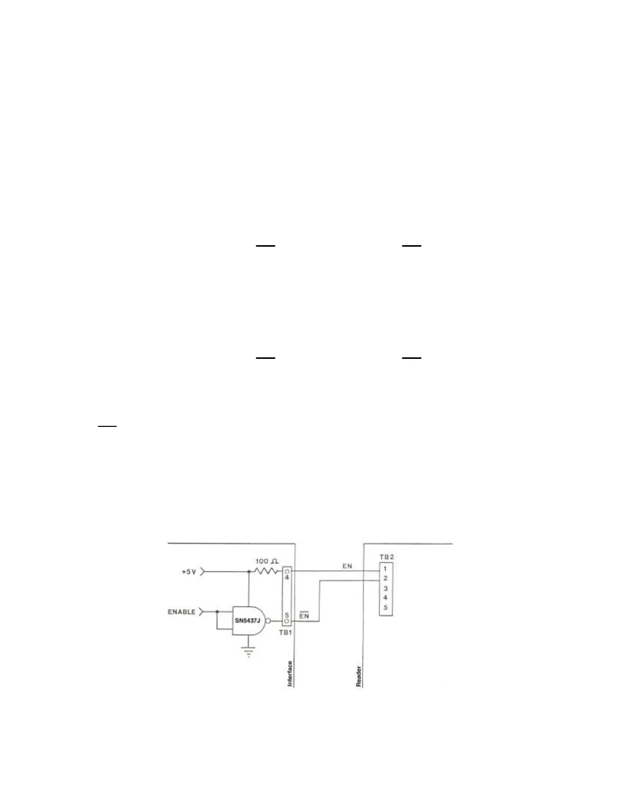
2.8 ABOUT ENABLE AND REMOTE ENABLE
The Reader operation may be controlled (enabled, disabled) from the Interface via the enable outputs
(EN, EN) to the Reader. This is termed remote enable. Alternatively, a shorting jumper or shunt may
be placed across J1 on the circuit board of the Reader assembly. The shunt overrides the remote
enable control and continuously enables the Reader. This feature is maintained primarily for us, the
manufacturer as a testing and quality control tool. It is not recommended for use outside of testing the
Reader. The Reader is not normally supplied with the shorting shunt installed on J1. Refer to your
Reader manual for specific instructions. The typical circuit connection for the remote enable feature is
shown below.