RFL Auxiliary Hybrid Chassis RFL Electronics Inc.
March 29, 2005 4 (973) 334-3100
CONTROLS AND INDICATORS
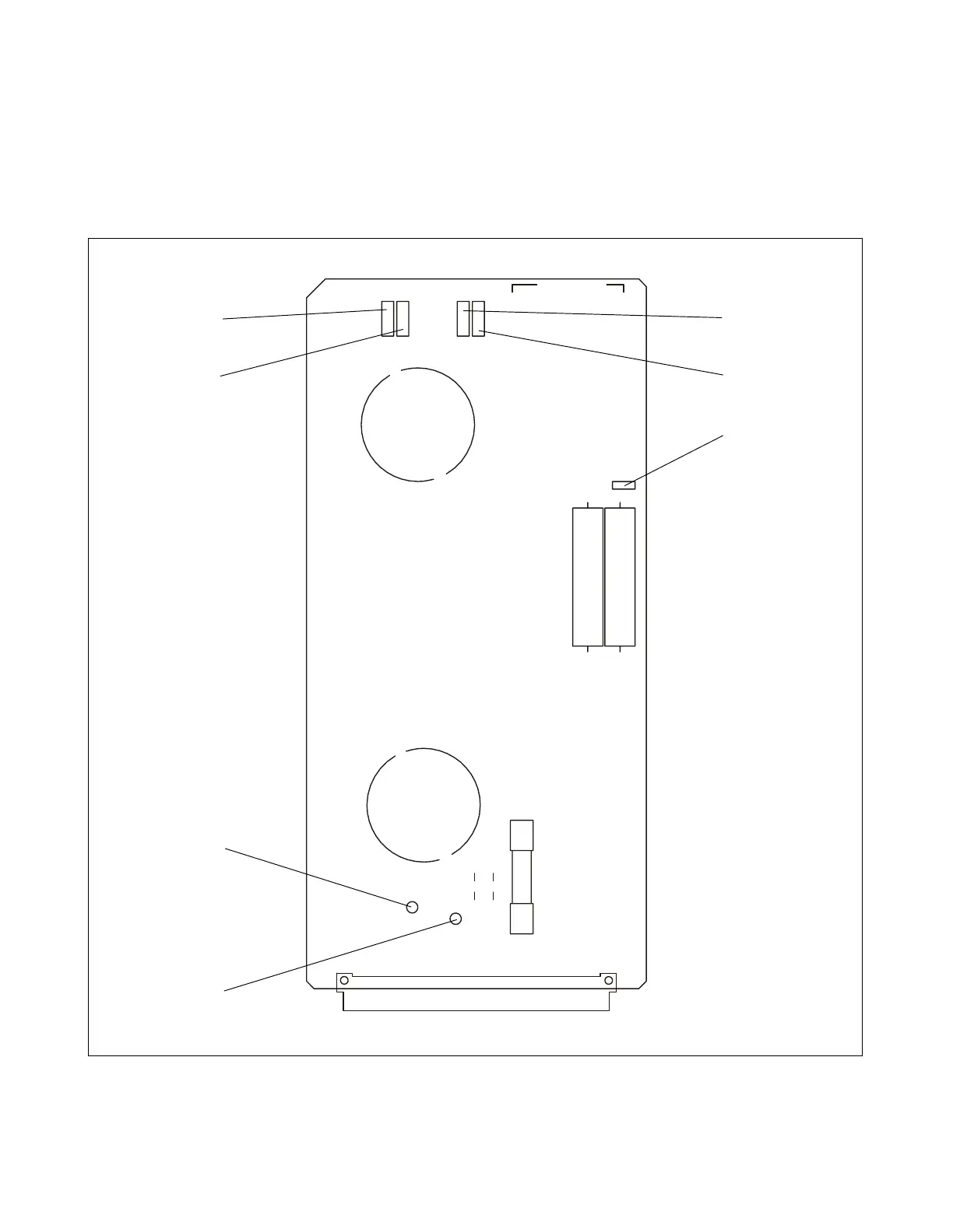
Figure 2 shows the location of all controls, indicators and components on the X-Hybrid Module. The
controls and indicators are described in Table 1. Only TP5, TP6, TP7 and TP8 are accessible with the
X-Hybrid Module installed in the chassis. All others are accessible when the module is removed from
the chassis or is on a card extender.
P1
L2
TP4
J1
R14
R13
F1
L1
TP3
TP5
TP6
TP7
TP8
9780/85 HYBRID ECB NO. 106623 REV-A
DUAL SINGLE
2000 RFL ELECTRONICS INC., BOONTON, NJ, U.S.A.
TX1 RXTX2
E
C
N
A
L
A
B
HI LOLOLO HIHI
B
A
32
AC
1
1
1
1
1
Figure 2. Controls, indicators, and component locations, X-Hybrid Module
TP8
TP7
J1
TP6
TP5
TP4
TP3